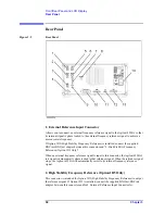


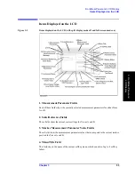


64
Chapter 4
Preparation of Measurement Accessories
Selecting Accessories for Measurement
Selecting Accessories for Measurement
Select the appropriate accessories (test fixture, adapter, probe, cable, etc.) for your
measurement in accordance with Table 4-1. Detailed specifications are described in
catalogs or in the operation manual of each accessory.
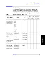
Table 4-1
Guidelines for Selecting Accessories
Type of
Device
Condition
Accessory
Features of Accessory
Lead
component
Entire frequency range of 4294A
16047E
Equipped with screws for firmly
fixing the fixture to the 4294A.
Entire frequency range of 4294A
42942A and 16092A
For both chip and lead
components.
Entire frequency range of 4294A
42942A and 16093A
Two binding-post-type
electrodes set 7 mm apart.
Entire frequency range of 4294A
42942A and 16093B
Three binding-post-type
electrodes set 15 mm and
18 mm apart.
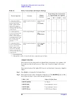
Frequency
£
40 MHz
16047C
Frequency
£
40 MHz
16047D
For axial and radial lead
components.
Frequency
£
13 MHz
16047A
For axial and radial lead
components.
Frequency
£
10 MHz, Balanced
component and circuit measurement
16314A
Three binding-post-type
electrodes.
Frequency
£
2 MHz, External dc bias
up to 200 V
16065A
For axial and radial lead
components. Equipped with
safety cover.
Frequency
£
100 kHz, Component
terminal diameter
£
15 mm
16089A
Two Kelvin clips.
Cable length: approx. 1 m.
Frequency
£
100 kHz, Component
terminal diameter
£
7.9 mm
16089B
Two Kelvin clips.
Cable length: approx. 1 m.
Frequency
£
100 kHz, Component
terminal diameter
£
6 mm
16089E
Two Kelvin clips.
Cable length: approx. 1 m.
Frequency
£
100 kHz, IC pin
diameter
£
1 mm
16089C
Two Kelvin clips.
Cable length: approx. 1 m.
Frequency
£
100 kHz
16089D
Four alligator clips.
Cable length: approx. 1 m.
Summary of Contents for 4294A
Page 1: ......
Page 2: ......
Page 4: ......
Page 5: ......
Page 6: ......
Page 8: ......
Page 16: ...8 ...
Page 30: ...22 Chapter1 Installation Power Cable Figure 1 2 Alternative Power Cable Options ...
Page 70: ...62 Chapter3 Front Rear Panel and LCD Display Items Displayed on the LCD ...
Page 436: ...428 AppendixB Key Definitions Softkeys displayed by pressing the Recall key ...
Page 454: ...446 AppendixC Error messages WRONG I O PORT DIRECTION ...
Page 468: ......


