


Chapter 8
219
Analysis and Processing of Result
Reading the difference from the reference point on the screen (delta marker)
8. A
nal
ys
is
a
nd P
roc
es
si
ng
of
Res
ult
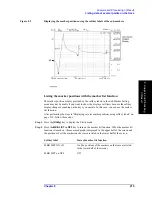
When you press the key, the current set value of the selected parameter indicating the delta
marker position is displayed in the Setting Parameter Value field in the upper left area of
the screen.
When the measurement parameter is COMPLEX Z-Y, there are two types of scalar
measurement parameters (primary measurement parameter and secondary measurement
parameter) for both trace A and trace B; therefore you set the measurement parameter
values of the delta marker with two keys:
FIXED
D
MKR VALUE
key and
FIXED
D
MKR
AUX VALUE
key. The definition of the primary measurement parameter and secondary
measurement parameter is shown in Table 8-1.
NOTE
If you have selected the delta-marker-on-the-trace mode (
D
MKR
key) in “Placing the delta
marker on the reference point with the main marker” on page 217, you cannot set the
measurement parameter value (
FIXED
D
MKR
key) or secondary measurement parameter
value (
FIXED
D
MKR AUX VALUE
key).
Step 5.
Use the keys or rotary knob of the ENTRY block in one of the following ways to specify
the position parameter of the delta marker you have selected.
•
Enter the desired value with the numeric keys (
[0]
to
[9]
[.]
and
[-]
) and then press one
of the unit keys (
[G/n]
,
[M/
m
]
,
[k/m]
, or
[
´
1]
).
•
Turn the rotary knob (
m
m
m
m
) until the desired value is set.
•
Press the step keys ([
][
¯
]) to set the desired value.
Step 6.
Repeat Step 4 and Step 5 to move the delta marker to the reference point.
NOTE
You cannot use the automatic move (search) function of the delta marker alone to move to
a point on the trace such as the maximum value, minimum value, target value, peak, and so
on. To move the delta marker to one of these points, follow the step shown in “Placing the
delta marker on the reference point with the main marker” on page 217.
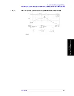
Displaying the main/sub-marker and reading the difference from the
reference point
After placing the delta marker at the reference point by following “Placing the delta marker
on the reference point with the main marker” on page 217 or “Moving the delta marker
alone to place it at a reference point” on page 218, display the main marker or sub-marker
on the trace and move it to the desired location.
For how to move the main marker, refer to related topics including:
Table 8-1
Definitions of primary and secondary parameters when measurement
parameter is COMPLEX Z-Y
Display format
Primary measurement
parameter
Secondary measurement
parameter
Complex plane
(COMPLEX)
Real part (R or G)
Imaginary part (X or B)
Polar coordinates
(POLAR)
Absolute value (|Z| or |Y|)
Phase (
q
Z
or
q
Y
)
Summary of Contents for 4294A
Page 1: ......
Page 2: ......
Page 4: ......
Page 5: ......
Page 6: ......
Page 8: ......
Page 16: ...8 ...
Page 30: ...22 Chapter1 Installation Power Cable Figure 1 2 Alternative Power Cable Options ...
Page 70: ...62 Chapter3 Front Rear Panel and LCD Display Items Displayed on the LCD ...
Page 436: ...428 AppendixB Key Definitions Softkeys displayed by pressing the Recall key ...
Page 454: ...446 AppendixC Error messages WRONG I O PORT DIRECTION ...
Page 468: ......


