


146
Chapter 6
Calibration
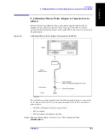
G. Calibration When the 3.5-mm Port of the 42941A is Extended
Step 2.
Perform the user calibration at the other end of the extended 3.5-mm port of the 42941A
Impedance Probe. You can use either the calibration kit supplied by Agilent Technologies
or a user-defined calibration kit. See “User Calibration” on page 147 for the user
calibration procedure.
Step 3.
Set the port extension value in electrical length or delay time, which is equivalent to the
electrical length between the user calibration plane and the device contacts of the test
fixture, in accordance with “Port Extension Compensation” on page 150.
NOTE
In measurements using the Agilent 4294A, the electrical length (delay time) of a 42942A
dedicated test fixture (such as 16092A) and 42941A’s dedicated probe adapter can be
regarded as 0.
Step 4.
Perform fixture compensation at the device contacts of the test fixture. See “Fixture
Compensation” on page 151 for the fixture compensation procedure.
NOTE
If user calibration in step 2 cannot be performed for some reason, set the port extension
value in electrical length or delay time, which is equivalent to the electrical length between
the 3.5-mm port of the 42941A and the device contacts of the test fixture, in place of steps
2 and 3, in accordance with “Port Extension Compensation” on page 150.
Summary of Contents for 4294A
Page 1: ......
Page 2: ......
Page 4: ......
Page 5: ......
Page 6: ......
Page 8: ......
Page 16: ...8 ...
Page 30: ...22 Chapter1 Installation Power Cable Figure 1 2 Alternative Power Cable Options ...
Page 70: ...62 Chapter3 Front Rear Panel and LCD Display Items Displayed on the LCD ...
Page 436: ...428 AppendixB Key Definitions Softkeys displayed by pressing the Recall key ...
Page 454: ...446 AppendixC Error messages WRONG I O PORT DIRECTION ...
Page 468: ......


