


260
Chapter 8
Analysis and Processing of Result
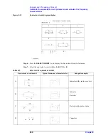
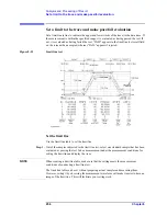
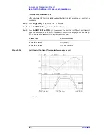
Set a limit to the trace and make pass/fail evaluation
(2) Move the main marker to the position of the segment stop value using the rotary knob
(
m
m
m
m
) or the step keys (
[
][
¯
]
).
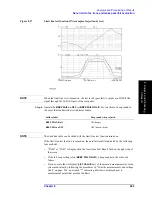
(3) Key operations of
more 1/3
-
more 2/3
-
MKR Æ VALUE STOP
allow the
measurement parameter value at the stop point of the trace to be substituted into the limit
range middle value. After setting in this order, press the
more 3/3
-
more 3/1
keys to go
back to the Segment Edit menu (2/3).
Step 18.
After the limit range is initially set by the upper value, press the
LOWER LIMIT
key. If it is
set by the middle value, press the
DELTA LIMIT
key. The lower limit of the limit range at
the stop point or limit width is displayed in the set parameter value field in the upper left
area of the screen.
Step 19.
Use the keys or rotary knob of the ENTRY block in one of the following ways to specify
the lower value or limit differential (ranges of upper limit value and lower limit value).
•
Enter the desired value with the numeric keys (
[0]
to
[9]
,
[-]
and
[.]
) and then press one
of the unit keys (
[G/n]
,
[M/
m
]
,
[k/m]
, or
[
´
1]
).
•
Turn the rotary knob (
m
m
m
m
) until the desired value is set.
•
Press the step keys ([
][
¯
]) to set the desired value.
This setting allows a new lower limit value or limit differential value to be written for the
lower limit value/differential value string (LOWER or DELTA) at the stop point on the line
of the segment being edited in the limit line table. If you need to turn off (make invalid) the
limit line test of the segment temporarily, press
more 2/3
-
TEST ON off
to change the
softkey label to
TEST on OFF
.
When the limit line test of the segment is turned off, the test will be regarded as having
passed even if it exceeds the limit range set by the measurement trace, and the limit line of
the segment will not be displayed. When the limit line test is off, * is displayed to the right
of the segment number in the completed limit line table. Note that * is not displayed when
the pointer (>) is displayed to the right of the segment number.
When a new segment is added, the limit line test is ON (
TEST ON off
) as default setting.
Step 20.
Press the
done
key to complete segment editing.
NOTE
To suspend editing of the segment and to return to the state before editing started, press the
cancel
key.
Step 21.
Repeat steps 7 to 21 to create the required number of segments. Use the following edit
function if required.
Limit line table edit function
Key operation
Select the segment number
(the currently selected segment is indicated by
“<“ indicated to the right of the segment
number (NO line).
SEGMENT
- (use the ENTRY block key to
enter)
Start the edit mode of the selected segment.
EDIT
Delete the selected segment (pressing the key
causes deletion immediately).
DELETE
Summary of Contents for 4294A
Page 1: ......
Page 2: ......
Page 4: ......
Page 5: ......
Page 6: ......
Page 8: ......
Page 16: ...8 ...
Page 30: ...22 Chapter1 Installation Power Cable Figure 1 2 Alternative Power Cable Options ...
Page 70: ...62 Chapter3 Front Rear Panel and LCD Display Items Displayed on the LCD ...
Page 436: ...428 AppendixB Key Definitions Softkeys displayed by pressing the Recall key ...
Page 454: ...446 AppendixC Error messages WRONG I O PORT DIRECTION ...
Page 468: ......


