


Chapter 8
261
Analysis and Processing of Result
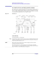
Set a limit to the trace and make pass/fail evaluation
8. A
nal
ys
is
a
nd P
roc
es
si
ng
of
Res
ult
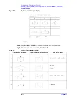
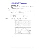
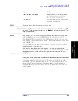
Figure 8-25
Completed limit line table
NOTE
From 1 to 18 segments can be set in the limit line table.
To set the limit range of the segment when an upper value is not required, set an extremely
large value that has no influence as an upper value. When a lower value is not required, set
an extremely small value that has no influence as a lower value.
The limit range of each segment can be set either as a combination of upper and lower limit
values or as a combination of middle and differential values. If the middle and differential
value setting keys are pressed for the limit range previously set in terms of upper and lower
limit values, or conversely if the upper and lower value setting keys are pressed for the
limit range set in terms of middle and differential values, then the format of the limit range
of the entire limit test table will be modified according to the most recently pressed keys.
When a new segment is added after the selected segment, it has the same value as that of
the immediately preceding segment.
Step 22.
After completion of the limit line table editing, press the
done
key of the Limit Line Edit
menu. To suspend editing, press the
cancel
key. In both cases, you will return to the Limit
Test menu.
NOTE
If you press the
cancel
key to suspend editing of the limit line table, you will return to the
contents of the limit line table that existed before entering the edit mode.
Add a new segment to the end of the selected
segment and start the edit mode of the
segment.
ADD
Delete all of the segments in the list sweep
table being edited.
CLEAR LIST
-
yes
(
cancel
)
Limit line table edit function
Key operation
Summary of Contents for 4294A
Page 1: ......
Page 2: ......
Page 4: ......
Page 5: ......
Page 6: ......
Page 8: ......
Page 16: ...8 ...
Page 30: ...22 Chapter1 Installation Power Cable Figure 1 2 Alternative Power Cable Options ...
Page 70: ...62 Chapter3 Front Rear Panel and LCD Display Items Displayed on the LCD ...
Page 436: ...428 AppendixB Key Definitions Softkeys displayed by pressing the Recall key ...
Page 454: ...446 AppendixC Error messages WRONG I O PORT DIRECTION ...
Page 468: ......


