Chapter 5. Power Supply / CPU
5-
13
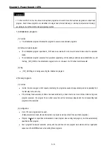
REMARK
∗
1: In the GLOFA PLC, the time driven interrupt task programs and event driven interrupt task programs are called task
program. Event driven programs are classified into single task (internal interrupt) or interrupt task (external interrupt)
according to the S/W and H/W interrupt signaling method.
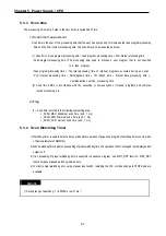
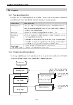
1) Initialization program
(1) Function
•
The Initialization program initializes the program to execute scan and task programs.
(2) Cold/warm restart program
•
The initialization program specified to _INIT task is executed with cold or warm restart mode when the operation
starts.
•
This initialization program executes the operations repeatedly until the setting conditions are satisfied (that is, until
the Flag _INIT_DONE in the initialization program turns on). However, the I/O refresh is still executed.
(3) Flag
•
_INIT_RUN flag is on during executing the initialization program.
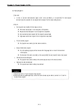
2) Scan program
(1) Function
•
In order to process signal, which repeats constantly, the program executes its sequential operation repeatedly from
the first step to the end step.
•
If the interrupt task execution condition has been satisfied by a time driven task or event driven task during scan
program execution, the program that is under execution will be temporary stopped and the corresponding task
program will be executed.
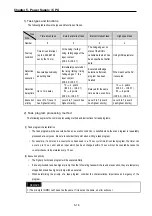
(2) Configuration
•
Up to 100 scan programs can be used.
(If task programs are used, the usable number is reduced as many as that of the used task programs)
•
Program has been not specified to initialization or task program when writing that program, it will be automatically
specified to scan program.
•
Scan program has lowest execution priority and the priorities of scan program are determined their registration
sequence in the GMWIN screen when writing those programs.
Содержание GLOFA G7M-DR20U
Страница 28: ...Chapter 4 Names of Parts 4 3 2 G7M DRT60U N 3 G7M DT60U N 4 G7M DT60U P...
Страница 29: ...Chapter 4 Names of Parts 4 4 5 G7M DR60U DC 6 G7M DRT60U N DC 7 G7M DT60U N DC...
Страница 30: ...Chapter 4 Names of Parts 4 5 8 G7M DT60U P DC 4 1 2 40 point main unit 1 G7M DR40U 2 G7M DRT40U N...
Страница 31: ...Chapter 4 Names of Parts 4 6 3 G7M DT40U N 4 G7M DT40U P 5 G7M DR40U DC...
Страница 32: ...Chapter 4 Names of Parts 4 7 6 G7M DRT40U N DC 7 G7M DT40U N DC 8 G7M DT40U P DC...
Страница 33: ...Chapter 4 Names of Parts 4 8 4 1 3 30 point main unit 1 G7M DR30U 2 G7M DRT30U N 3 G7M DT30U N...
Страница 34: ...Chapter 4 Names of Parts 4 9 4 G7M DT30U P 5 G7M DR30U DC 6 G7M DRT30U N DC...
Страница 35: ...Chapter 4 Names of Parts 4 10 7 G7M DT30U N DC 8 G7M DT30U P DC 4 1 4 20 point main unit 1 G7M DR20U...
Страница 36: ...Chapter 4 Names of Parts 4 11 2 G7M DRT20U N 3 G7M DT20U N 4 G7M DT20U P...
Страница 37: ...Chapter 4 Names of Parts 4 12 5 G7M DR20U DC 6 G7M DRT20U N DC 7 G7M DT20U N DC...
Страница 38: ...Chapter 4 Names of Parts 4 13 8 G7M DT20U P DC...
Страница 159: ...Chapter 7 Usage of Various Functions 7 52 c Program...
Страница 183: ...Chapter 7 Usage of Various Functions 7 76 c Program...
Страница 253: ...Chapter 8 Communication Functions 8 27 b When uses Ch 1 Built in RS 485...
Страница 355: ...Appendix 1 System Definitions App1 8 5 PID parameters 1 PID Auto Tuning Parameter 2 PID Parameter...
Страница 356: ...Appendix 1 System Definitions App1 9 6 Position Parameter...
Страница 357: ...Appendix 1 System Definitions App1 10 7 High Speed Counter Parameter...


