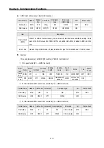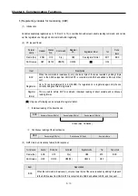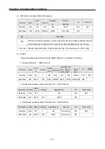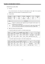
Chapter 8. Communication Functions
8-13
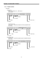
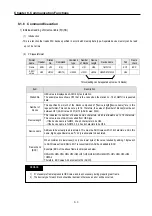
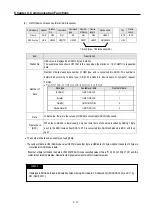
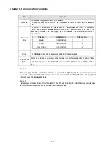
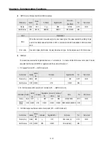
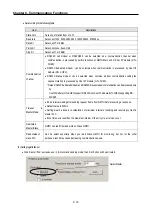
Item
Description
Station No.
HEX value is displayed as ASCII 2 bytes in station.
The example above shows H10 that is the case when the station no. 16 of GM7U is requested
data.
Number of
data
The number of data means the byte to respond. It is converted into ASCII. This number is
determined by multiplying the data number of the computer request format by the data size (in the
table below) according to the memory type (B, W, D) included in the variable name of computer
request format.
Data
The HEX data in respond data area converted to ASCII code are saved.
Frame check
(BCC)
When the command is lowercase(r), only one lower byte of the value resulted by adding 1 Byte
each to the ASCII values from ACK to ETX is converted into ASCII and added to BCC, and then
sent.
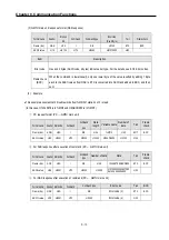
Example 1)
When memory type included in variable name of computer request Format is W(Word), and data number of computer request
Format is 03, data number of PLC ACK response after execution of command is indicated by H06(2*03 = 06 bytes)Byte and
ASCII code value 3036 is entered in data area.
Example 2)
In just above example, when data contents of 3 words are 1234, 5678, and 9ABC in order, actual ASCII code converted values
are 31323334 35363738 39414243, and the contents are entered in data area.
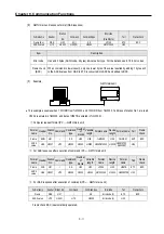
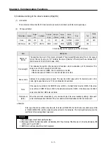
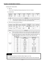
Data type
Available device
Data size (byte)
Byte(B) %MB,%QB,%IB
1
Word(W) %MW,%QW,%IW
2
Double Word(D)
%MD,%QD,%ID
4
Содержание GLOFA G7M-DR20U
Страница 28: ...Chapter 4 Names of Parts 4 3 2 G7M DRT60U N 3 G7M DT60U N 4 G7M DT60U P...
Страница 29: ...Chapter 4 Names of Parts 4 4 5 G7M DR60U DC 6 G7M DRT60U N DC 7 G7M DT60U N DC...
Страница 30: ...Chapter 4 Names of Parts 4 5 8 G7M DT60U P DC 4 1 2 40 point main unit 1 G7M DR40U 2 G7M DRT40U N...
Страница 31: ...Chapter 4 Names of Parts 4 6 3 G7M DT40U N 4 G7M DT40U P 5 G7M DR40U DC...
Страница 32: ...Chapter 4 Names of Parts 4 7 6 G7M DRT40U N DC 7 G7M DT40U N DC 8 G7M DT40U P DC...
Страница 33: ...Chapter 4 Names of Parts 4 8 4 1 3 30 point main unit 1 G7M DR30U 2 G7M DRT30U N 3 G7M DT30U N...
Страница 34: ...Chapter 4 Names of Parts 4 9 4 G7M DT30U P 5 G7M DR30U DC 6 G7M DRT30U N DC...
Страница 35: ...Chapter 4 Names of Parts 4 10 7 G7M DT30U N DC 8 G7M DT30U P DC 4 1 4 20 point main unit 1 G7M DR20U...
Страница 36: ...Chapter 4 Names of Parts 4 11 2 G7M DRT20U N 3 G7M DT20U N 4 G7M DT20U P...
Страница 37: ...Chapter 4 Names of Parts 4 12 5 G7M DR20U DC 6 G7M DRT20U N DC 7 G7M DT20U N DC...
Страница 38: ...Chapter 4 Names of Parts 4 13 8 G7M DT20U P DC...
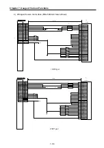
Страница 159: ...Chapter 7 Usage of Various Functions 7 52 c Program...
Страница 183: ...Chapter 7 Usage of Various Functions 7 76 c Program...
Страница 253: ...Chapter 8 Communication Functions 8 27 b When uses Ch 1 Built in RS 485...
Страница 355: ...Appendix 1 System Definitions App1 8 5 PID parameters 1 PID Auto Tuning Parameter 2 PID Parameter...
Страница 356: ...Appendix 1 System Definitions App1 9 6 Position Parameter...
Страница 357: ...Appendix 1 System Definitions App1 10 7 High Speed Counter Parameter...

