


Chapter 8. Communication Functions
8-23
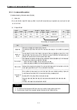
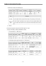
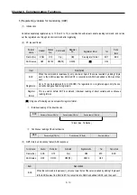
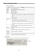
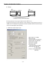
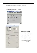
7) Reading PLC Status (RST)
(1)
Introduction
This is a function that reads flag list including operating status of PLC and error information.
(2)
PC request format
Format name
Header
Station No.
Command
Command type
Tail
Frame check
Frame (Ex.)
ENQ
H0A
R(r)
ST
EOT
BCC
ASCII
value
H05 H3041
H52(72)
H5354 H04
Item
Description
BCC
When command is lowercase(r), only one lower byte of the value resulted by adding 1 Byte each
to ASCII values from ENQ to EOT is converted into ASCII and added to BCC.
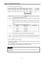
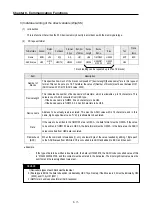
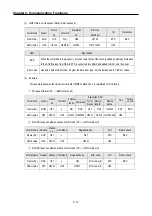
(3)
GM7U main unit response format (ACK response)
Format name
Header
Station
No.
Command
Command type
PLC status data
(Hex 20 Byte)
Tail
Frame check
Frame (Ex.)
ACK
H0A
R(r)
ST
Status data format
ETX
BCC
ASCII value
H06
H304
1
H52(72)
H5354
[ ]
※
H03
Item
Description
BCC
When the command is lowercase(r), only one lower byte of the value resulted by adding 1 Byte
each to ASCII values from ACK to ETX is converted into ASCII, and then added to BCC, and sent.
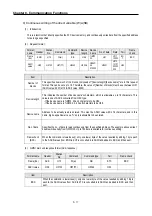
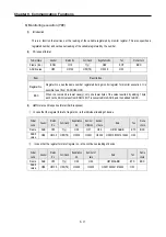
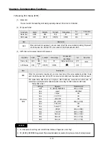
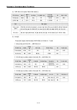
PLC status
data
PLC status data: data format is 20 bytes in HEX format and converted into ASCII code. Its
contents are constituted as the table below after converting the ASCII code into HEX code.
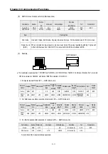
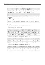
※
Status data format
1) For the details of each flag, refer to GM7U User's Manual "Appendix 2, list of flag".
2) PC_DEVICE_IDENTIFIER, Logical, and Physical are dedicated to be used only for system, so it should not be processed.
REMARK
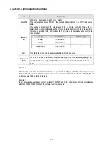
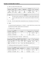
Data type
Flag name
Status data order
UINT
PC_DEVICE_IDENTIFIER;
H00(L) ~ H01(H)
Byte Logical;
H02(Offset)
Byte Physical;
H03
Byte _CPU_TYPE;
H04
Byte _VER_NUM;
H05
Word
_SYS_STATE;
H06(L) ~ H07(H)
Byte _PADT_CNF;
H08
Byte _Domain_ST;
H09
Word
_CNF_ER;
H0A(L) ~ H0B(H)
Word
_CNF_WR;
H0C(L) ~ H0D(H)
Word
Reserved
H0E(L) ~ H0F(H)
Word
Reserved
H10(L) ~ H11(H)
Word
Reserved
H12(L) ~ H13(H)
Содержание GLOFA G7M-DR20U
Страница 28: ...Chapter 4 Names of Parts 4 3 2 G7M DRT60U N 3 G7M DT60U N 4 G7M DT60U P...
Страница 29: ...Chapter 4 Names of Parts 4 4 5 G7M DR60U DC 6 G7M DRT60U N DC 7 G7M DT60U N DC...
Страница 30: ...Chapter 4 Names of Parts 4 5 8 G7M DT60U P DC 4 1 2 40 point main unit 1 G7M DR40U 2 G7M DRT40U N...
Страница 31: ...Chapter 4 Names of Parts 4 6 3 G7M DT40U N 4 G7M DT40U P 5 G7M DR40U DC...
Страница 32: ...Chapter 4 Names of Parts 4 7 6 G7M DRT40U N DC 7 G7M DT40U N DC 8 G7M DT40U P DC...
Страница 33: ...Chapter 4 Names of Parts 4 8 4 1 3 30 point main unit 1 G7M DR30U 2 G7M DRT30U N 3 G7M DT30U N...
Страница 34: ...Chapter 4 Names of Parts 4 9 4 G7M DT30U P 5 G7M DR30U DC 6 G7M DRT30U N DC...
Страница 35: ...Chapter 4 Names of Parts 4 10 7 G7M DT30U N DC 8 G7M DT30U P DC 4 1 4 20 point main unit 1 G7M DR20U...
Страница 36: ...Chapter 4 Names of Parts 4 11 2 G7M DRT20U N 3 G7M DT20U N 4 G7M DT20U P...
Страница 37: ...Chapter 4 Names of Parts 4 12 5 G7M DR20U DC 6 G7M DRT20U N DC 7 G7M DT20U N DC...
Страница 38: ...Chapter 4 Names of Parts 4 13 8 G7M DT20U P DC...
Страница 159: ...Chapter 7 Usage of Various Functions 7 52 c Program...
Страница 183: ...Chapter 7 Usage of Various Functions 7 76 c Program...
Страница 253: ...Chapter 8 Communication Functions 8 27 b When uses Ch 1 Built in RS 485...
Страница 355: ...Appendix 1 System Definitions App1 8 5 PID parameters 1 PID Auto Tuning Parameter 2 PID Parameter...
Страница 356: ...Appendix 1 System Definitions App1 9 6 Position Parameter...
Страница 357: ...Appendix 1 System Definitions App1 10 7 High Speed Counter Parameter...


