Chapter 8. Communication Functions
8-15
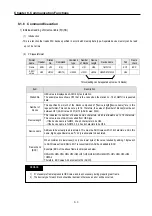
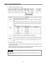
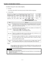
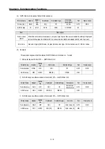
3) Individual writing of the direct variable (W(w)SS)
(1)
Introduction
This is a function that writes the PLC device memory directly in accordance with the memory data type.
(2)
PC request format
Format name Header
Station
No.
Command
Comman
d type
Number
of blocks
Device
Length
Device
Name
Data
Tail
Frame
check
Frame ENQ
H10 R(r) SS H01 H06
%MW100
H00E2
...
EOT BCC
ASCII value
H05
H313
0
H52(72) H5353
H3031
H3036
H254D57
313030
H3030
4532
H04
1 block (setting can be repeated up to max. 16 blocks)
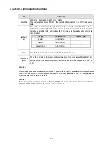
Item
Description
Number of
blocks
This specifies how much of the blocks composed of "[device length][device name]" are in this request
format. This can be set up to 16. Therefore, the value of [Number of blocks] must be set between H01
(ASCII value: 3031)-H10 (ASCII value: 3030).
Device length
This indicates the number of device name's characters, which is allowable up to 16 characters. This
value is one of ASCII converted from HEX type,
- If the device name is %MW0, it has 4 characters to be H04.
- If the device name is %QW0.0.0, it has 8 characters to be H08.
Device name
Address to be actually read is entered. This must be ASCII value within 16 characters, and in this
name, digits, upper/lower case, '%' only is allowable to be entered.
Data
If the value to be written in the %MW100 area is HEX A, the data format must be H000A. If the value
to be written in %MW100 area is HEX A, the data format must be H000A. In the data area, the ASCII
value converted from HEX data is entered.
Frame check
(BCC)
When the command is lowercase(r), only one lower byte of the value resulted by adding 1 Byte each
to the ASCII values from ENQ to EOT is converted into ASCII and added to BCC, and then sent.
•
Example
-
If the type of data to be written is double word, the data is H12345678, the ASCII code converted value of this
is “3132333435363738, and this content must be entered in the data area. The most significant value must be
sent first and the least significant value last.
1) Device data types of each block must be identical.
2) If data type is BOOL, the data to be written is indicated by HEX 1 bye. Namely, if the bit value is 0, it must be indicate by H00
(3030), and if 1, by H01 (3031)
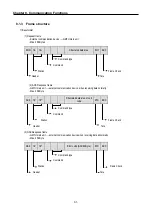
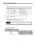
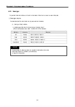
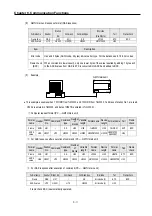
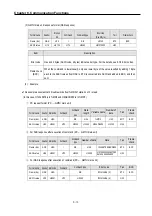
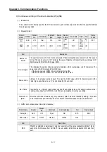
3) GM7U main unit response format (ACK response)
REMARK
Содержание GLOFA G7M-DR20U
Страница 28: ...Chapter 4 Names of Parts 4 3 2 G7M DRT60U N 3 G7M DT60U N 4 G7M DT60U P...
Страница 29: ...Chapter 4 Names of Parts 4 4 5 G7M DR60U DC 6 G7M DRT60U N DC 7 G7M DT60U N DC...
Страница 30: ...Chapter 4 Names of Parts 4 5 8 G7M DT60U P DC 4 1 2 40 point main unit 1 G7M DR40U 2 G7M DRT40U N...
Страница 31: ...Chapter 4 Names of Parts 4 6 3 G7M DT40U N 4 G7M DT40U P 5 G7M DR40U DC...
Страница 32: ...Chapter 4 Names of Parts 4 7 6 G7M DRT40U N DC 7 G7M DT40U N DC 8 G7M DT40U P DC...
Страница 33: ...Chapter 4 Names of Parts 4 8 4 1 3 30 point main unit 1 G7M DR30U 2 G7M DRT30U N 3 G7M DT30U N...
Страница 34: ...Chapter 4 Names of Parts 4 9 4 G7M DT30U P 5 G7M DR30U DC 6 G7M DRT30U N DC...
Страница 35: ...Chapter 4 Names of Parts 4 10 7 G7M DT30U N DC 8 G7M DT30U P DC 4 1 4 20 point main unit 1 G7M DR20U...
Страница 36: ...Chapter 4 Names of Parts 4 11 2 G7M DRT20U N 3 G7M DT20U N 4 G7M DT20U P...
Страница 37: ...Chapter 4 Names of Parts 4 12 5 G7M DR20U DC 6 G7M DRT20U N DC 7 G7M DT20U N DC...
Страница 38: ...Chapter 4 Names of Parts 4 13 8 G7M DT20U P DC...
Страница 159: ...Chapter 7 Usage of Various Functions 7 52 c Program...
Страница 183: ...Chapter 7 Usage of Various Functions 7 76 c Program...
Страница 253: ...Chapter 8 Communication Functions 8 27 b When uses Ch 1 Built in RS 485...
Страница 355: ...Appendix 1 System Definitions App1 8 5 PID parameters 1 PID Auto Tuning Parameter 2 PID Parameter...
Страница 356: ...Appendix 1 System Definitions App1 9 6 Position Parameter...
Страница 357: ...Appendix 1 System Definitions App1 10 7 High Speed Counter Parameter...

