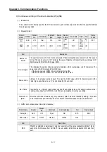
Chapter 8. Communication Functions
8-25
8.1.7 1:1, 1:N Built-in communications between LSIS products
1)
Introduction
1:1 built-in communication between GM7U's is that which constitutes a built-in communication system with the method of
1(master): 1(slave). Setting Base parameter and communication parameter in GMWIN can easily constitute this system.
Communication protocol currently applied is the same with Cnet I/F used for GLOFA. Main functions are following.
•
It can organize input (I), output (Q), and internal memory (M) area into 64 data access blocks by WORD unit, and set a
communication time-out limit for each block.
•
Up to 32 stations can be connected. (When using built-in RS-485 (Ch. 1), G7L-CUEC)
•
It can reestablish flag in relation with error codes and slave PLC operating mode according to parameter setting.
•
It can reset flag related with error codes and sending/receiving error frequency of each parameter.
•
It monitors communication status, using monitoring function of GMWIN.
•
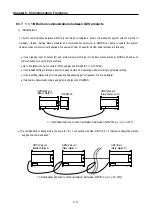
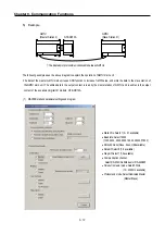
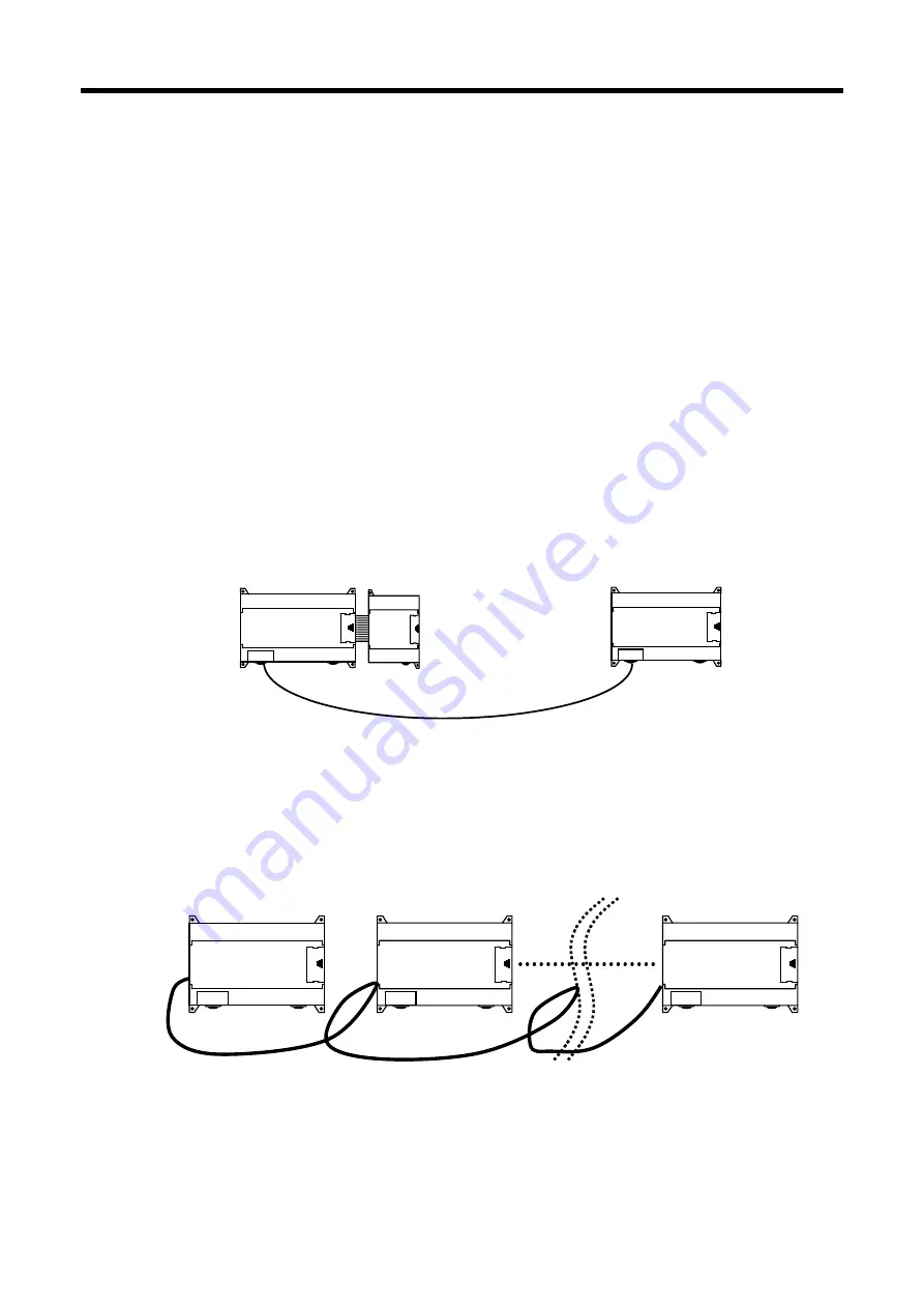
This communication cabling map is the same for (3) 1:1 connecting with other GM7U in 8.1.2 "System configuration method
using built-in communication."
GM7U Main unit
(Slave: Station no. 31)
GM7U Main unit
(Master: Station 1)
G7E-DR10A
1:1
dedicated protocol communication between GM7U’s (
using RS-232C
)
GM7U main unit
(Master: Station 0)
1:N
dedicated protocol communication between GM7U’s (
using RS-485C
)
GM7U main unit
(Slave: Station 1)
GM7U main
(Slave: Station 31)
Содержание GLOFA G7M-DR20U
Страница 28: ...Chapter 4 Names of Parts 4 3 2 G7M DRT60U N 3 G7M DT60U N 4 G7M DT60U P...
Страница 29: ...Chapter 4 Names of Parts 4 4 5 G7M DR60U DC 6 G7M DRT60U N DC 7 G7M DT60U N DC...
Страница 30: ...Chapter 4 Names of Parts 4 5 8 G7M DT60U P DC 4 1 2 40 point main unit 1 G7M DR40U 2 G7M DRT40U N...
Страница 31: ...Chapter 4 Names of Parts 4 6 3 G7M DT40U N 4 G7M DT40U P 5 G7M DR40U DC...
Страница 32: ...Chapter 4 Names of Parts 4 7 6 G7M DRT40U N DC 7 G7M DT40U N DC 8 G7M DT40U P DC...
Страница 33: ...Chapter 4 Names of Parts 4 8 4 1 3 30 point main unit 1 G7M DR30U 2 G7M DRT30U N 3 G7M DT30U N...
Страница 34: ...Chapter 4 Names of Parts 4 9 4 G7M DT30U P 5 G7M DR30U DC 6 G7M DRT30U N DC...
Страница 35: ...Chapter 4 Names of Parts 4 10 7 G7M DT30U N DC 8 G7M DT30U P DC 4 1 4 20 point main unit 1 G7M DR20U...
Страница 36: ...Chapter 4 Names of Parts 4 11 2 G7M DRT20U N 3 G7M DT20U N 4 G7M DT20U P...
Страница 37: ...Chapter 4 Names of Parts 4 12 5 G7M DR20U DC 6 G7M DRT20U N DC 7 G7M DT20U N DC...
Страница 38: ...Chapter 4 Names of Parts 4 13 8 G7M DT20U P DC...
Страница 159: ...Chapter 7 Usage of Various Functions 7 52 c Program...
Страница 183: ...Chapter 7 Usage of Various Functions 7 76 c Program...
Страница 253: ...Chapter 8 Communication Functions 8 27 b When uses Ch 1 Built in RS 485...
Страница 355: ...Appendix 1 System Definitions App1 8 5 PID parameters 1 PID Auto Tuning Parameter 2 PID Parameter...
Страница 356: ...Appendix 1 System Definitions App1 9 6 Position Parameter...
Страница 357: ...Appendix 1 System Definitions App1 10 7 High Speed Counter Parameter...

