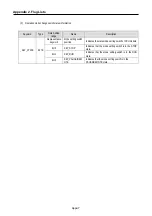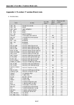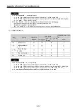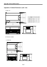
Appendix 2. Flag Lists
App2-3
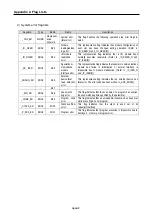
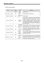
3) System warning flag lists
Keyword
Type
Bit No.
Name
Description
_CNF _WAR
WORD
Representative
keyword
System
warning
This flag treats the below warning flags relating to continuous
operation in batch.
_RTC_ERR
BOOL
Bit 0
RTC data
error
This flag indicates that RTC DATA error.
_D_BCK_ER BOOL
Bit
1
Data backup
error
This flag indicates
_AB_SD_ER BOOL
Bit
3
Abnormal
shutdown
This flag indicates that the program had been stopped during
restore from power failure due to causes such as power off,
and then cold restart has been executed and the
continuous operation which retains the data is impossible.
Usable in the initialization program. Automatically reset when
the initialization program has finished. (The same things given
above will be applied when the program has been stopped by
the ‘ESTOP’ function)
_TASK_ERR BOOL
Bit
4
Task collision
(plus cycle
and external
tasks)
This flag indicates that task collision has occurred as
execution request for a same task had been repeatedly
invoked. (Refer to the flag _TC_BMAP[n] and _TC_CNT[n])
_BAT_ERR
BOOL
Bit 5
Battery fault
This flag detects and indicates that the voltage of the battery,
which is used to backup user programs and data memory, is
lower than the defined value.
_ANNUN_WR BOOL
Bit
6
External
device
warning
detection
This representative flag indicates that the user program has
detected an ordinary fault of external devices and has written
it to the flag _ANC_WB [n].
−
−
Bit 7
−
−
_HSPMT1_ER BOOL
Bit
8
Communica-
tion
Parameter 1
error
This representative flag detects error of each Communication
parameter when the Communication has been enabled and
indicates that Communication cannot be executed. It will be
reset when the Communication is disabled.
Содержание GLOFA G7M-DR20U
Страница 28: ...Chapter 4 Names of Parts 4 3 2 G7M DRT60U N 3 G7M DT60U N 4 G7M DT60U P...
Страница 29: ...Chapter 4 Names of Parts 4 4 5 G7M DR60U DC 6 G7M DRT60U N DC 7 G7M DT60U N DC...
Страница 30: ...Chapter 4 Names of Parts 4 5 8 G7M DT60U P DC 4 1 2 40 point main unit 1 G7M DR40U 2 G7M DRT40U N...
Страница 31: ...Chapter 4 Names of Parts 4 6 3 G7M DT40U N 4 G7M DT40U P 5 G7M DR40U DC...
Страница 32: ...Chapter 4 Names of Parts 4 7 6 G7M DRT40U N DC 7 G7M DT40U N DC 8 G7M DT40U P DC...
Страница 33: ...Chapter 4 Names of Parts 4 8 4 1 3 30 point main unit 1 G7M DR30U 2 G7M DRT30U N 3 G7M DT30U N...
Страница 34: ...Chapter 4 Names of Parts 4 9 4 G7M DT30U P 5 G7M DR30U DC 6 G7M DRT30U N DC...
Страница 35: ...Chapter 4 Names of Parts 4 10 7 G7M DT30U N DC 8 G7M DT30U P DC 4 1 4 20 point main unit 1 G7M DR20U...
Страница 36: ...Chapter 4 Names of Parts 4 11 2 G7M DRT20U N 3 G7M DT20U N 4 G7M DT20U P...
Страница 37: ...Chapter 4 Names of Parts 4 12 5 G7M DR20U DC 6 G7M DRT20U N DC 7 G7M DT20U N DC...
Страница 38: ...Chapter 4 Names of Parts 4 13 8 G7M DT20U P DC...
Страница 159: ...Chapter 7 Usage of Various Functions 7 52 c Program...
Страница 183: ...Chapter 7 Usage of Various Functions 7 76 c Program...
Страница 253: ...Chapter 8 Communication Functions 8 27 b When uses Ch 1 Built in RS 485...
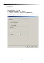
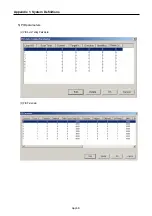
Страница 355: ...Appendix 1 System Definitions App1 8 5 PID parameters 1 PID Auto Tuning Parameter 2 PID Parameter...
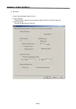
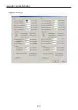
Страница 356: ...Appendix 1 System Definitions App1 9 6 Position Parameter...
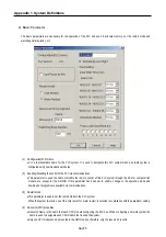
Страница 357: ...Appendix 1 System Definitions App1 10 7 High Speed Counter Parameter...

