Chapter 7. Usage of Various Functions
7-91
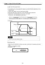
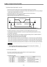
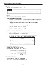
10) External Input Stroke High / Low Limit
•
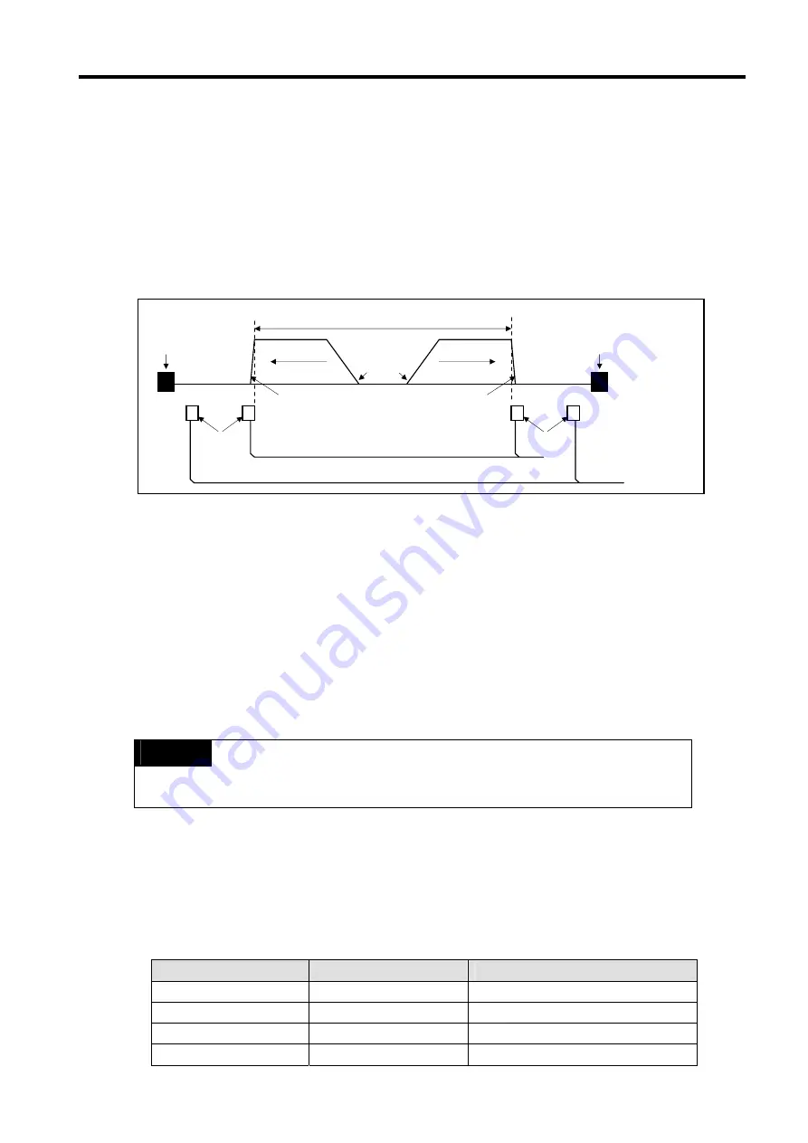
External input stroke limit includes External input high limit signal and External input low limit signal.
•
This is used to stop the positioning function promptly before reaching Stroke limit/Stroke End of the Driver by installing the
stroke limit inside Stroke limit/Stroke end of the Driver.
•
If it deviates the high limit, Error H53 will occur and if it deviates the low limit, Error H54 will occur.
•
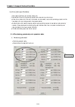
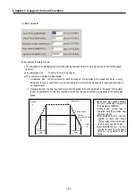
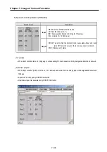
External input stroke limit can be set in GMWIN parameter
•
High/Low limit input contact point is fixed to P0,P1 for ch0 and P2,P3 for ch1.
•
If positioning module stops out of the range available to control, the positioning operation does not work.
If it stops by external input stroke limit detection, move within the range of positioning module available to control by
manual operation (Jog operation).
•
As external input stroke high/low limit error is detected by the edge of positioning module, it is available to release the
output prohibit out of stroke range and carry out manual operation.
•
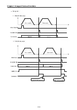
The flags related with external input stroke limit are as followings.
- %IX0.0.0 (Ch0) Off : External input stroke Low limit has not detected, On : External input stroke Low limit has detected
- %IX0.0.1 (Ch0) Off : External input stroke High limit has not detected, On : External input stroke High limit has detected
- %IX0.0.2 (Ch1) Off : External input stroke Low limit has not detected, On : External input stroke Low limit has detected
- %IX0.0.3 (Ch1) Off : External input stroke High limit has not detected, On : External input stroke High limit has detected
REMARK
If external input stroke High/Low limit signal is occur during origin return, it stops operation immediately,
Then, changes direction and continues origin return operation.
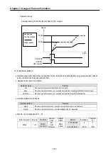
11) M Code (After mode)
This is the mode that sets M Code Set bit when the M Code Enable bit is On after completing the positioning.
To operate the next step, the M Code Set bit must be reset.
•
Special relays are as follow.
Area
Description
Remark
0 bit of %MW4319
M Code Enable Bit (Ch0)
Set M Code when it is On
1 bit of %MW4319
M Code Set Bit (Ch0)
Set when the positioning is completed
0 bit of %MW4519
M Code Enable Bit (Ch1)
Set M Code when it is On
1 bit of %MW4519
M Code Set Bit (Ch1)
Set when the positioning is completed
Transfer direction
Transfer direction
Start
Start
High Low
Limit switch
Limit switch
GM7U
Driver
Stopper
Stopper
The range available to positioning
Immediate stop when
Detecting the high limit
Immediate stop when
Detecting the low limit
Содержание GLOFA G7M-DR20U
Страница 28: ...Chapter 4 Names of Parts 4 3 2 G7M DRT60U N 3 G7M DT60U N 4 G7M DT60U P...
Страница 29: ...Chapter 4 Names of Parts 4 4 5 G7M DR60U DC 6 G7M DRT60U N DC 7 G7M DT60U N DC...
Страница 30: ...Chapter 4 Names of Parts 4 5 8 G7M DT60U P DC 4 1 2 40 point main unit 1 G7M DR40U 2 G7M DRT40U N...
Страница 31: ...Chapter 4 Names of Parts 4 6 3 G7M DT40U N 4 G7M DT40U P 5 G7M DR40U DC...
Страница 32: ...Chapter 4 Names of Parts 4 7 6 G7M DRT40U N DC 7 G7M DT40U N DC 8 G7M DT40U P DC...
Страница 33: ...Chapter 4 Names of Parts 4 8 4 1 3 30 point main unit 1 G7M DR30U 2 G7M DRT30U N 3 G7M DT30U N...
Страница 34: ...Chapter 4 Names of Parts 4 9 4 G7M DT30U P 5 G7M DR30U DC 6 G7M DRT30U N DC...
Страница 35: ...Chapter 4 Names of Parts 4 10 7 G7M DT30U N DC 8 G7M DT30U P DC 4 1 4 20 point main unit 1 G7M DR20U...
Страница 36: ...Chapter 4 Names of Parts 4 11 2 G7M DRT20U N 3 G7M DT20U N 4 G7M DT20U P...
Страница 37: ...Chapter 4 Names of Parts 4 12 5 G7M DR20U DC 6 G7M DRT20U N DC 7 G7M DT20U N DC...
Страница 38: ...Chapter 4 Names of Parts 4 13 8 G7M DT20U P DC...
Страница 159: ...Chapter 7 Usage of Various Functions 7 52 c Program...
Страница 183: ...Chapter 7 Usage of Various Functions 7 76 c Program...
Страница 253: ...Chapter 8 Communication Functions 8 27 b When uses Ch 1 Built in RS 485...
Страница 355: ...Appendix 1 System Definitions App1 8 5 PID parameters 1 PID Auto Tuning Parameter 2 PID Parameter...
Страница 356: ...Appendix 1 System Definitions App1 9 6 Position Parameter...
Страница 357: ...Appendix 1 System Definitions App1 10 7 High Speed Counter Parameter...

