Chapter 7. Usage of Various Functions
7-98
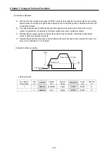
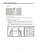
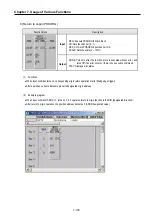
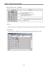
(1) Step No.
•
The setting range of positioning data as serial no. is 1
∼
20.
REMARK
If step No. set to 0, operating step increase to next step automatically when current operation step finished
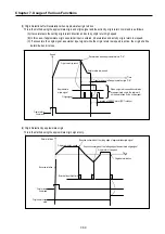
(2) Coordinate
•
The coordinate of position data includes Absolute and Incremental
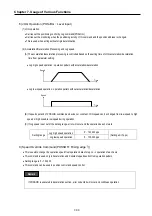
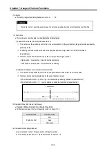
(A) Absolute Coordinate (Control by Absolute method)
①
This carries out the positioning control from the current position to the goal position (the goal position assigned by
positioning data).
②
Positioning control is carried out based on the assigned position of origin return or POSPRS command
(origin address).
③
Transfer direction shall be determined by the current position and goal position.
- Start position < Goal position : forward direction positioning
- Start position > Goal position : reverse direction positioning
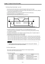
(B) Relative Coordinate (Control by Incremental method)
①
This carries out the positioning control as much as goal transfer amount from the current position.
②
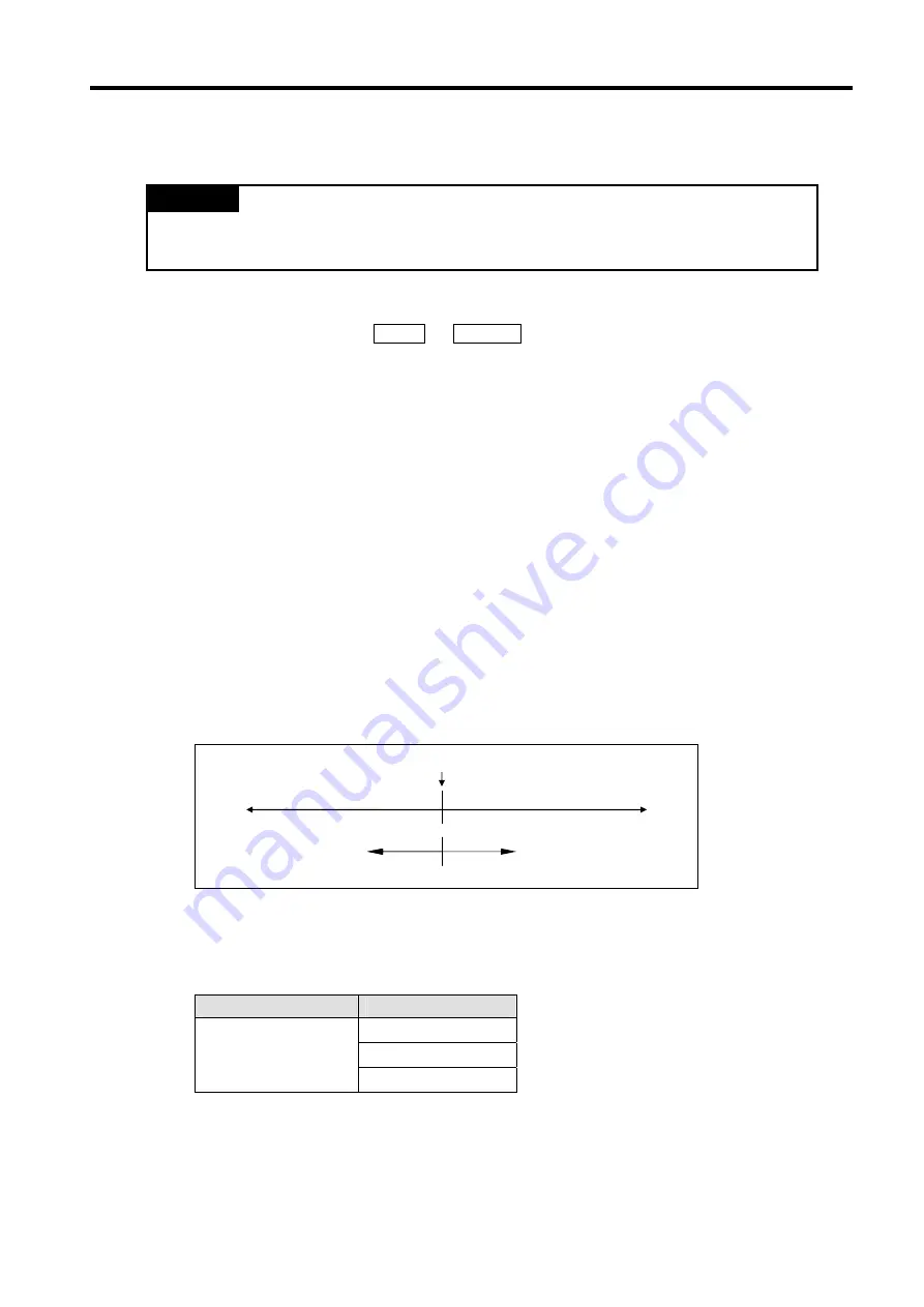
Transfer direction shall be determined by the sign of transfer amount.
- When transfer direction is (+) or no sign : normal direction positioning (position increase direction)
- When transfer direction is ( - ) : reverse direction positioning (position decrease direction)
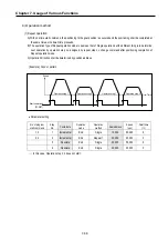
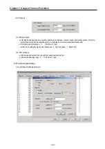
(3) Operation Mode (End / Keep / Continuous)
•
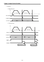
Operation Mode is divided into following three kinds.
•
For the details, please refer to ‘3) Operation mode’ in chapter 7.3.2
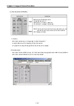
Control method
Operation mode
End
Keep
Position control
Continuous
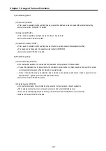
(4) Operation Method (Single/Repeat)
•
Select operation method : Single operation or Repeat operation.
•
For the details, please refer to ‘4) Operation method’ in chapter 7.3.2.
Current position
Transfer direction when transfer amount is (+)
Transfer direction when transfer amount is (-)
Reverse
Normal
Содержание GLOFA G7M-DR20U
Страница 28: ...Chapter 4 Names of Parts 4 3 2 G7M DRT60U N 3 G7M DT60U N 4 G7M DT60U P...
Страница 29: ...Chapter 4 Names of Parts 4 4 5 G7M DR60U DC 6 G7M DRT60U N DC 7 G7M DT60U N DC...
Страница 30: ...Chapter 4 Names of Parts 4 5 8 G7M DT60U P DC 4 1 2 40 point main unit 1 G7M DR40U 2 G7M DRT40U N...
Страница 31: ...Chapter 4 Names of Parts 4 6 3 G7M DT40U N 4 G7M DT40U P 5 G7M DR40U DC...
Страница 32: ...Chapter 4 Names of Parts 4 7 6 G7M DRT40U N DC 7 G7M DT40U N DC 8 G7M DT40U P DC...
Страница 33: ...Chapter 4 Names of Parts 4 8 4 1 3 30 point main unit 1 G7M DR30U 2 G7M DRT30U N 3 G7M DT30U N...
Страница 34: ...Chapter 4 Names of Parts 4 9 4 G7M DT30U P 5 G7M DR30U DC 6 G7M DRT30U N DC...
Страница 35: ...Chapter 4 Names of Parts 4 10 7 G7M DT30U N DC 8 G7M DT30U P DC 4 1 4 20 point main unit 1 G7M DR20U...
Страница 36: ...Chapter 4 Names of Parts 4 11 2 G7M DRT20U N 3 G7M DT20U N 4 G7M DT20U P...
Страница 37: ...Chapter 4 Names of Parts 4 12 5 G7M DR20U DC 6 G7M DRT20U N DC 7 G7M DT20U N DC...
Страница 38: ...Chapter 4 Names of Parts 4 13 8 G7M DT20U P DC...
Страница 159: ...Chapter 7 Usage of Various Functions 7 52 c Program...
Страница 183: ...Chapter 7 Usage of Various Functions 7 76 c Program...
Страница 253: ...Chapter 8 Communication Functions 8 27 b When uses Ch 1 Built in RS 485...
Страница 355: ...Appendix 1 System Definitions App1 8 5 PID parameters 1 PID Auto Tuning Parameter 2 PID Parameter...
Страница 356: ...Appendix 1 System Definitions App1 9 6 Position Parameter...
Страница 357: ...Appendix 1 System Definitions App1 10 7 High Speed Counter Parameter...


