Chapter 7. Usage of Various Functions
7-70
7.2.5 RTD input module
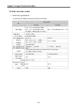
1) Performance specification
The performance specifications of the RTD input module are following
.
Item
Specifications
Connectable RTD
Pt 100 (JIS C1640-1989, DIN 43760-1980)
JPt100 (KS C1603-1991, JIS C1604-1981)
Temperature input
range
Pt 100: -200 ~ 600 (18.48 to 313.59
℃
Ω
)
JPt100: -200 ~ 600 (17.14 to 317.28
℃
Ω
)
Digital output
Digital conversion value: 0 ~ 4,000
Detected temperature value: -2000~6000(one digit after point X 10)
Burn out detection
Three wires at every channel has detection function respectively
Accuracy ±0.5%
[Full Scale]
Maximum conversion
speed
40 scan / all channel
Temperature input point 4 channel / 1 module
No. of module
installation
Max. 3 modules
Insulation
Photo-coupler insulation between the input terminal and the PLC power
supply (non-insulation between channels)
Connection terminal
block
2 of 8 points terminal
Current consumption 25
㎃
Voltage DC 21.6 26.4V
∼
External power
supply
Current 70
㎃
Weight 240g
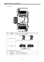
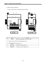
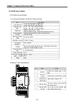
2) Names of parts and functions
No.
Name
Function
①
RUN
LED
Indicates the operating status of G7F-
RD2A.
②
RTD input
terminal
Terminal which connects Pt100 or JPt100
③
External power
input terminal
Supply external voltage DC 24V
④
Extension
cable
This cable is used to connect while RTD
input module is used.
④
Extension cable
connector
The connector connects extension cable
when extended module is used.
③
②
①
④
②
⑤
24V
B
A
b
·
B
A
b
·
A
b
B
A
b
24G
G7F-RD2A
PROGRAMMABLE
LOGIC
CONTROLLER
CH2
CH3
Input
CH0
CH1
PWR
B
Содержание GLOFA G7M-DR20U
Страница 28: ...Chapter 4 Names of Parts 4 3 2 G7M DRT60U N 3 G7M DT60U N 4 G7M DT60U P...
Страница 29: ...Chapter 4 Names of Parts 4 4 5 G7M DR60U DC 6 G7M DRT60U N DC 7 G7M DT60U N DC...
Страница 30: ...Chapter 4 Names of Parts 4 5 8 G7M DT60U P DC 4 1 2 40 point main unit 1 G7M DR40U 2 G7M DRT40U N...
Страница 31: ...Chapter 4 Names of Parts 4 6 3 G7M DT40U N 4 G7M DT40U P 5 G7M DR40U DC...
Страница 32: ...Chapter 4 Names of Parts 4 7 6 G7M DRT40U N DC 7 G7M DT40U N DC 8 G7M DT40U P DC...
Страница 33: ...Chapter 4 Names of Parts 4 8 4 1 3 30 point main unit 1 G7M DR30U 2 G7M DRT30U N 3 G7M DT30U N...
Страница 34: ...Chapter 4 Names of Parts 4 9 4 G7M DT30U P 5 G7M DR30U DC 6 G7M DRT30U N DC...
Страница 35: ...Chapter 4 Names of Parts 4 10 7 G7M DT30U N DC 8 G7M DT30U P DC 4 1 4 20 point main unit 1 G7M DR20U...
Страница 36: ...Chapter 4 Names of Parts 4 11 2 G7M DRT20U N 3 G7M DT20U N 4 G7M DT20U P...
Страница 37: ...Chapter 4 Names of Parts 4 12 5 G7M DR20U DC 6 G7M DRT20U N DC 7 G7M DT20U N DC...
Страница 38: ...Chapter 4 Names of Parts 4 13 8 G7M DT20U P DC...
Страница 159: ...Chapter 7 Usage of Various Functions 7 52 c Program...
Страница 183: ...Chapter 7 Usage of Various Functions 7 76 c Program...
Страница 253: ...Chapter 8 Communication Functions 8 27 b When uses Ch 1 Built in RS 485...
Страница 355: ...Appendix 1 System Definitions App1 8 5 PID parameters 1 PID Auto Tuning Parameter 2 PID Parameter...
Страница 356: ...Appendix 1 System Definitions App1 9 6 Position Parameter...
Страница 357: ...Appendix 1 System Definitions App1 10 7 High Speed Counter Parameter...

