


Chapter 7. Usage of Various Functions
7-26
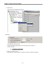
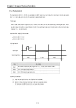
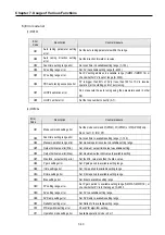
3) Function block
For the PID operation of GM7U, following 2 instructions are included in the GMWIN software.
No.
Name
Description
1
PID7CAL
Perform the PID operation
2
PID7AT
Perform the auto tuning operation
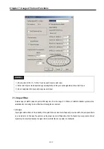
1)
Array is not supported for GM7U PID function block.
2)
For details, refer to the GMWIN user’s manual.
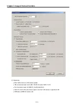
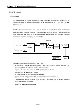
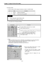
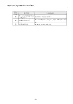
(1)
The function block for PID operation (PID7CAL)
Function block
Description
Input
EN: enables PID7CAL function block (Level operation)
LOOP: sets execution loop (0~7)
Output
DONE: On when the execution is finished without an error. Off when an
error occurred or there is not execution request
SV: outputs current SV (set value) (range: 0~4000)
MV: outputs MV (manipulation value) ( range: 0 ~ 4000 )
STAT: outputs error code
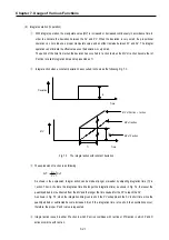
a) Usage
•
When the condition of the execution is On, PID operation is executed following the set values of the parameter.
(The PID operation does not operate at the edge, it operates while the execution condition is On.)
•
LOOP No. (LOOP) designates the PID operation LOOP no. (0~7)
•
Stat disignates the area where the PID Operation loop’s status is saved.
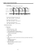
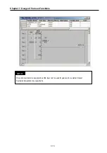
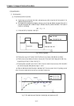
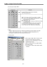
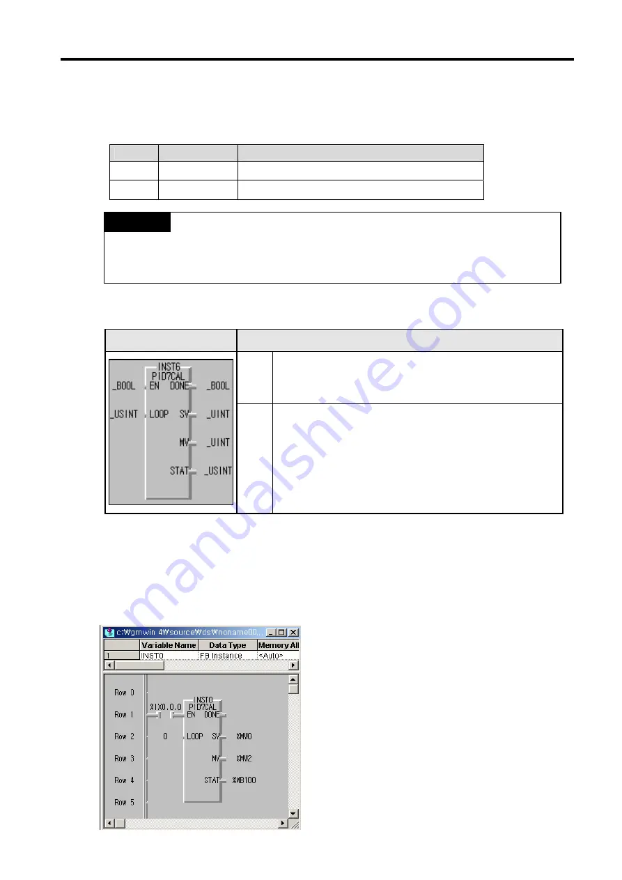
b)
Program example
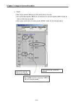
REMARK
•
When the input codition %IX0.0.0 turns On, the PID
operation starts following the parameters.
•
The satus during the PID operation is saved
in %MB100, and the PID control output value (MV) is
saved in %MW2.
•
For SV Ramp function, the changing SV is save
in %MW0.
Содержание GLOFA G7M-DR20U
Страница 28: ...Chapter 4 Names of Parts 4 3 2 G7M DRT60U N 3 G7M DT60U N 4 G7M DT60U P...
Страница 29: ...Chapter 4 Names of Parts 4 4 5 G7M DR60U DC 6 G7M DRT60U N DC 7 G7M DT60U N DC...
Страница 30: ...Chapter 4 Names of Parts 4 5 8 G7M DT60U P DC 4 1 2 40 point main unit 1 G7M DR40U 2 G7M DRT40U N...
Страница 31: ...Chapter 4 Names of Parts 4 6 3 G7M DT40U N 4 G7M DT40U P 5 G7M DR40U DC...
Страница 32: ...Chapter 4 Names of Parts 4 7 6 G7M DRT40U N DC 7 G7M DT40U N DC 8 G7M DT40U P DC...
Страница 33: ...Chapter 4 Names of Parts 4 8 4 1 3 30 point main unit 1 G7M DR30U 2 G7M DRT30U N 3 G7M DT30U N...
Страница 34: ...Chapter 4 Names of Parts 4 9 4 G7M DT30U P 5 G7M DR30U DC 6 G7M DRT30U N DC...
Страница 35: ...Chapter 4 Names of Parts 4 10 7 G7M DT30U N DC 8 G7M DT30U P DC 4 1 4 20 point main unit 1 G7M DR20U...
Страница 36: ...Chapter 4 Names of Parts 4 11 2 G7M DRT20U N 3 G7M DT20U N 4 G7M DT20U P...
Страница 37: ...Chapter 4 Names of Parts 4 12 5 G7M DR20U DC 6 G7M DRT20U N DC 7 G7M DT20U N DC...
Страница 38: ...Chapter 4 Names of Parts 4 13 8 G7M DT20U P DC...
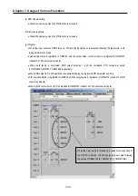
Страница 159: ...Chapter 7 Usage of Various Functions 7 52 c Program...
Страница 183: ...Chapter 7 Usage of Various Functions 7 76 c Program...
Страница 253: ...Chapter 8 Communication Functions 8 27 b When uses Ch 1 Built in RS 485...
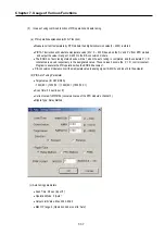
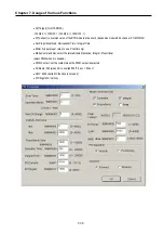
Страница 355: ...Appendix 1 System Definitions App1 8 5 PID parameters 1 PID Auto Tuning Parameter 2 PID Parameter...
Страница 356: ...Appendix 1 System Definitions App1 9 6 Position Parameter...
Страница 357: ...Appendix 1 System Definitions App1 10 7 High Speed Counter Parameter...


