


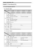


Chapter 5. Power Supply / CPU
5-2
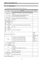
5.2
CPU Specifications
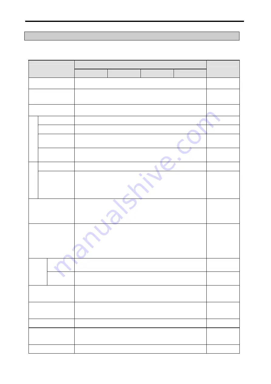
The following table shows the general specifications of the GLOFA–GM7U series.
Specifications
Items
20-point Main Unit 30-point Main Unit 40-point Main Unit 60-point Main Unit
Remarks
Operation method
Cycle execution of stored program, Time-driven interrupt, Process-driven
interrupt
I/O control method
Scan synchronized batch processing method (Refresh method),
Direct input/output method by input/output function
Program language
Instruction List, Ladder Diagram, Sequential Function Chart
Operator
LD: 13, IL: 21
Standard function
138
Standard function
block
11
Numbers of inst
ructions
Special function
block
Function blocks for built-in functions, special, communication modules
Operator
0.1 ~ 0.9
μ
s
Proce
ssing spee
d
Standard
function/function
block
Refer to the section Appendix 3
Program memory capacity 132K byte
Including
parameter
(Approx. 8K bytes)
I/O points
•
20-point main unit: 12-point input/8-point output
•
30-point main unit: 18-point input/ 12-point output
•
40-point main unit: 24-point input/ 16-point output
•
60-point main unit: 36-point input/ 24-point output
Max. of 3
expansion
modules can be
attached
I/O point: 20~120
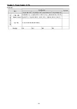
Data
Direct variable
area
14K Byte
Memory
Symbolic
variable area
30K Byte
Timer
No limitation,
Time range: 0.001~4,294,967.295 sec(1,193 hours)
Counter
No limitation,
Count range: -32,768 ~ +32,767
Operation mode
RUN, STOP, PAUSE, DEBUG
Data retention at power
failure
Set to ‘Retain’ at data declaration
Number of program blocks 100
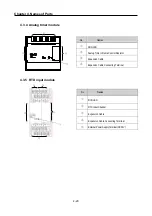
Содержание GLOFA G7M-DR20U
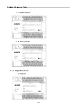
Страница 28: ...Chapter 4 Names of Parts 4 3 2 G7M DRT60U N 3 G7M DT60U N 4 G7M DT60U P...
Страница 29: ...Chapter 4 Names of Parts 4 4 5 G7M DR60U DC 6 G7M DRT60U N DC 7 G7M DT60U N DC...
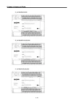
Страница 30: ...Chapter 4 Names of Parts 4 5 8 G7M DT60U P DC 4 1 2 40 point main unit 1 G7M DR40U 2 G7M DRT40U N...
Страница 31: ...Chapter 4 Names of Parts 4 6 3 G7M DT40U N 4 G7M DT40U P 5 G7M DR40U DC...
Страница 32: ...Chapter 4 Names of Parts 4 7 6 G7M DRT40U N DC 7 G7M DT40U N DC 8 G7M DT40U P DC...
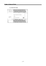
Страница 33: ...Chapter 4 Names of Parts 4 8 4 1 3 30 point main unit 1 G7M DR30U 2 G7M DRT30U N 3 G7M DT30U N...
Страница 34: ...Chapter 4 Names of Parts 4 9 4 G7M DT30U P 5 G7M DR30U DC 6 G7M DRT30U N DC...
Страница 35: ...Chapter 4 Names of Parts 4 10 7 G7M DT30U N DC 8 G7M DT30U P DC 4 1 4 20 point main unit 1 G7M DR20U...
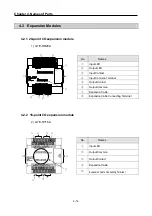
Страница 36: ...Chapter 4 Names of Parts 4 11 2 G7M DRT20U N 3 G7M DT20U N 4 G7M DT20U P...
Страница 37: ...Chapter 4 Names of Parts 4 12 5 G7M DR20U DC 6 G7M DRT20U N DC 7 G7M DT20U N DC...
Страница 38: ...Chapter 4 Names of Parts 4 13 8 G7M DT20U P DC...
Страница 159: ...Chapter 7 Usage of Various Functions 7 52 c Program...
Страница 183: ...Chapter 7 Usage of Various Functions 7 76 c Program...
Страница 253: ...Chapter 8 Communication Functions 8 27 b When uses Ch 1 Built in RS 485...
Страница 355: ...Appendix 1 System Definitions App1 8 5 PID parameters 1 PID Auto Tuning Parameter 2 PID Parameter...
Страница 356: ...Appendix 1 System Definitions App1 9 6 Position Parameter...
Страница 357: ...Appendix 1 System Definitions App1 10 7 High Speed Counter Parameter...


