Chapter 8. Communication Function
8-76
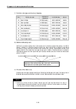
4) MOD1516
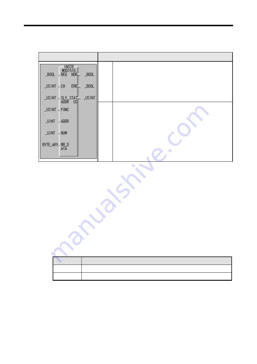
Function block
Description
Input
REQ: Execute function block when it’s 1(rising edge)
CH : Set communication channel (0 ~ 1)
SLV_ADDR: Input the number of the slave station
FUNC: Input the function code. It supports function code 15 and 16
ADDR: The starting address to read from the slave station
NUM: The data size to read from
the slave station
Output
WD_DATA: A variable name to save the data to be written.
NDR: If it ends without error, output 1 and keep the value till the call for the next
function block.
ERR: If an error occurs, output 1 and keep the value till the call for the next
function block.
STATUS: When an error occurs, output an error code.
(1)
Function
This is a function block that can execute either function code 15 or 16 for writing 1 bit (function code 15) and
writing 1 word (function code 16) in Modbus protocol communication. Function code 15 does 1 bit by 1 bit data
writing on each Coil in a sequence Coils. And Function 16 does 1 word by 1 word data writing on sequence of the
Holding Registers.
(2)
Error
It outputs error codes to output STATUS. Refer to “Error codes” for the detailed.
(3) Example of the program
z
It’s supposed that GM7U main unit is the master and it writes bits continually on the output coil of the
station no. 17, a Modicon product.
z
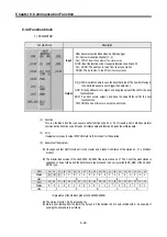
The master writes continual 10 bits, 01110011011 on the Coils 00020 of the slave station no. 17 1 bit
by 1 bit. The data that is to be written are saved in any array variable WR_DB0 of the 2 sized BYTE
type.
Variable
Value to save
WR_DB0 [0]
2#11001101 or 16#CD
WR_DB0 [1]
2#10000001 or 16#81
z
The size of BYTE_CNT is the same as when the data to be written are converted by byte. The above
data are 10 by 1 bit. They can’t be filled by 1 byte. So they must be filled from the low bit, using 2 bytes.
And 0 fills the remnant 6 bits. Therefore the size of BYTE_CNT is 2.
z
f it is supposed that data of 1000 0001 1100 1101 are saved in the array variable, WR_DB0, the data are
sent as 10 bits (01 1100 1101) at the bottom plus 6 bit of 0 at the top. For the size of the data is set as 10
bits to send and they are sent by bytes, the deficient 6 bits are filled with 0.
z
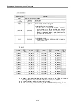
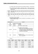
Data is sent starting from the low bit by byte unit. An example of sending the above data is as follows.
Содержание GLOFA G7M-DR20U
Страница 28: ...Chapter 4 Names of Parts 4 3 2 G7M DRT60U N 3 G7M DT60U N 4 G7M DT60U P...
Страница 29: ...Chapter 4 Names of Parts 4 4 5 G7M DR60U DC 6 G7M DRT60U N DC 7 G7M DT60U N DC...
Страница 30: ...Chapter 4 Names of Parts 4 5 8 G7M DT60U P DC 4 1 2 40 point main unit 1 G7M DR40U 2 G7M DRT40U N...
Страница 31: ...Chapter 4 Names of Parts 4 6 3 G7M DT40U N 4 G7M DT40U P 5 G7M DR40U DC...
Страница 32: ...Chapter 4 Names of Parts 4 7 6 G7M DRT40U N DC 7 G7M DT40U N DC 8 G7M DT40U P DC...
Страница 33: ...Chapter 4 Names of Parts 4 8 4 1 3 30 point main unit 1 G7M DR30U 2 G7M DRT30U N 3 G7M DT30U N...
Страница 34: ...Chapter 4 Names of Parts 4 9 4 G7M DT30U P 5 G7M DR30U DC 6 G7M DRT30U N DC...
Страница 35: ...Chapter 4 Names of Parts 4 10 7 G7M DT30U N DC 8 G7M DT30U P DC 4 1 4 20 point main unit 1 G7M DR20U...
Страница 36: ...Chapter 4 Names of Parts 4 11 2 G7M DRT20U N 3 G7M DT20U N 4 G7M DT20U P...
Страница 37: ...Chapter 4 Names of Parts 4 12 5 G7M DR20U DC 6 G7M DRT20U N DC 7 G7M DT20U N DC...
Страница 38: ...Chapter 4 Names of Parts 4 13 8 G7M DT20U P DC...
Страница 159: ...Chapter 7 Usage of Various Functions 7 52 c Program...
Страница 183: ...Chapter 7 Usage of Various Functions 7 76 c Program...
Страница 253: ...Chapter 8 Communication Functions 8 27 b When uses Ch 1 Built in RS 485...
Страница 355: ...Appendix 1 System Definitions App1 8 5 PID parameters 1 PID Auto Tuning Parameter 2 PID Parameter...
Страница 356: ...Appendix 1 System Definitions App1 9 6 Position Parameter...
Страница 357: ...Appendix 1 System Definitions App1 10 7 High Speed Counter Parameter...


