Chapter 7. Usage of Various Functions
7-3
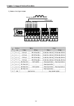
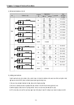
4) External interface circuit
Signal name
I/O
Internal circuit
Terminal
No.
1Phase
2Phase
Operation
Input
warranted
voltage
On 20.4~28.8V
I00
Ch0
Input
pulse
Ch0 A
Phase
Input
Off
6V or lower
On 20.4~28.8V
I01
Ch1
Input
pulse
Ch0 B
Phase
Input
Off 6V
or
lower
On 20.4~28.8V
I02
Ch2
Input
pulse
Ch2 A
Phase
Input
Off
6V or lower
On 20.4~28.8V
I03
Ch3
Input
pulse
Ch2 B
Phase
Input
Off 6V
or
lower
Input
COM0 Common
On 20.4~28.8V
I04
Ch0
Preset
input
Ch0
Preset
input
Off
6V or lower
On 20.4~28.8V
I05
Ch1
Preset
input
-
Off
6V or lower
On 20.4~28.8V
I06
Ch2
Preset
input
Ch2
Preset
input
Off
6V or lower
On 20.4~28.8V
I007
Ch3
Preset
input
-
Off
6V or lower
Input
COM0 Common
5) Wiring instructions
A high speed pulse input is sensitive to the external noise and should be handled with special care. When wiring the built-in
high speed counter of GM7U, take the following precautions against wiring noise.
(1) Be sure to use shielded twisted pair cables. Also provide Class 3 grounding.
(2) Do not run a twisted pair cable in parallel with power cables or other I/O lines which may generate noise.
(3) Before applying a power source for pulse generator, be sure to use a noise-protected power supply.
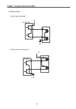
(4) For 1-phase input, connect the count input signal only to the phase A input; for 2-phase input, connect to phases A and B.
3.3 k
Ω
3.3 k
Ω
3.3 k
Ω
3.3 k
Ω
3.3 k
Ω
3.3 k
Ω
3.3 k
Ω
3.3 k
Ω
Содержание GLOFA G7M-DR20U
Страница 28: ...Chapter 4 Names of Parts 4 3 2 G7M DRT60U N 3 G7M DT60U N 4 G7M DT60U P...
Страница 29: ...Chapter 4 Names of Parts 4 4 5 G7M DR60U DC 6 G7M DRT60U N DC 7 G7M DT60U N DC...
Страница 30: ...Chapter 4 Names of Parts 4 5 8 G7M DT60U P DC 4 1 2 40 point main unit 1 G7M DR40U 2 G7M DRT40U N...
Страница 31: ...Chapter 4 Names of Parts 4 6 3 G7M DT40U N 4 G7M DT40U P 5 G7M DR40U DC...
Страница 32: ...Chapter 4 Names of Parts 4 7 6 G7M DRT40U N DC 7 G7M DT40U N DC 8 G7M DT40U P DC...
Страница 33: ...Chapter 4 Names of Parts 4 8 4 1 3 30 point main unit 1 G7M DR30U 2 G7M DRT30U N 3 G7M DT30U N...
Страница 34: ...Chapter 4 Names of Parts 4 9 4 G7M DT30U P 5 G7M DR30U DC 6 G7M DRT30U N DC...
Страница 35: ...Chapter 4 Names of Parts 4 10 7 G7M DT30U N DC 8 G7M DT30U P DC 4 1 4 20 point main unit 1 G7M DR20U...
Страница 36: ...Chapter 4 Names of Parts 4 11 2 G7M DRT20U N 3 G7M DT20U N 4 G7M DT20U P...
Страница 37: ...Chapter 4 Names of Parts 4 12 5 G7M DR20U DC 6 G7M DRT20U N DC 7 G7M DT20U N DC...
Страница 38: ...Chapter 4 Names of Parts 4 13 8 G7M DT20U P DC...
Страница 159: ...Chapter 7 Usage of Various Functions 7 52 c Program...
Страница 183: ...Chapter 7 Usage of Various Functions 7 76 c Program...
Страница 253: ...Chapter 8 Communication Functions 8 27 b When uses Ch 1 Built in RS 485...
Страница 355: ...Appendix 1 System Definitions App1 8 5 PID parameters 1 PID Auto Tuning Parameter 2 PID Parameter...
Страница 356: ...Appendix 1 System Definitions App1 9 6 Position Parameter...
Страница 357: ...Appendix 1 System Definitions App1 10 7 High Speed Counter Parameter...


