


Chapter 8. Communication Function
8-74
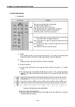
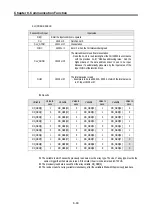
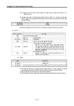
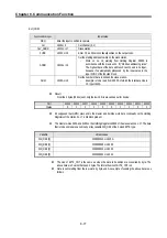
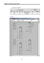
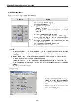
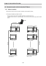
3) MOD0506
Function block
Description
Input
REQ: Execute function block when it’s 1(rising edge)
CH : Set communication channel (0 ~ 1)
SLV_ADDR: Input the number of the slave station
FUNC: Input the function code. It supports function code 05 and 06
ADDR: The starting address to read from the slave station
Output
DATA (J): A variable name to save the data to write.
NDR: If it ends without error, output 1 and keep the value till the call for the next
function block.
ERR: If an error occurs, output 1 and keep the value till the call for the next
function block.
STATUS: When an error occurs, output an error code.
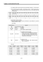
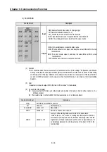
(1)
Function
This is a function block that can execute either function code 05 or 06 for writing 1 bit (function code 05) and
writing 1 word (function code 06) in Modbus protocol communication. Function code 05 does 1 bit data writing
on the Output Coil. If the Input NUMH is set as 255 (or HFF), it writes 1 on the output coil. If the Input NUMH is
set as 0 (or 16#00), it writes 0 on the output coil. And function 06 writes 1 word data on the Output Holding
Register.
(2)
Error
It outputs error codes to output STATUS. Refer to “Error codes” for the detailed.
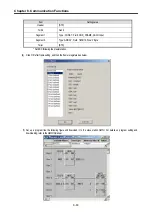
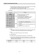
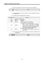
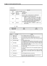
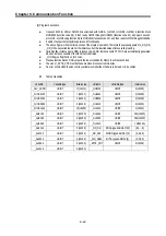
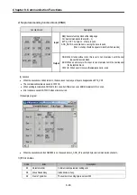
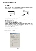
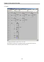
(3)
An example of the program
z
It assumes that GM7U main unit is the master and it writes 1 bit data on the Coil of the station no. 17, a
Modicon product.
z
The master writes 1 on the Coil 00173 of the slave station no. 17, a Modicon product.
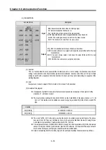
Function block input
Input value
REQ
Enter the input condition to operate
CH
16#0 or 0
Set channel (0, 1)
SLV_ADDR
16#11 or 17
Slave station
FUNC
16#05 or 5
Enter ‘5’ as writes 1 bit on the Coil.
ADDR
16#AC or 172
Low byte of the starting addresses to write on the slave station.
Write on the no. 172 to write on, starting from the output coil 00173 in
accordance with the previous no. 8) “Modbus addressing rules.” And the
highest data of the data address doesn’t need to be input. Because it’s
automatically processed by the input value of the input FUNC of the
function block.
Содержание GLOFA G7M-DR20U
Страница 28: ...Chapter 4 Names of Parts 4 3 2 G7M DRT60U N 3 G7M DT60U N 4 G7M DT60U P...
Страница 29: ...Chapter 4 Names of Parts 4 4 5 G7M DR60U DC 6 G7M DRT60U N DC 7 G7M DT60U N DC...
Страница 30: ...Chapter 4 Names of Parts 4 5 8 G7M DT60U P DC 4 1 2 40 point main unit 1 G7M DR40U 2 G7M DRT40U N...
Страница 31: ...Chapter 4 Names of Parts 4 6 3 G7M DT40U N 4 G7M DT40U P 5 G7M DR40U DC...
Страница 32: ...Chapter 4 Names of Parts 4 7 6 G7M DRT40U N DC 7 G7M DT40U N DC 8 G7M DT40U P DC...
Страница 33: ...Chapter 4 Names of Parts 4 8 4 1 3 30 point main unit 1 G7M DR30U 2 G7M DRT30U N 3 G7M DT30U N...
Страница 34: ...Chapter 4 Names of Parts 4 9 4 G7M DT30U P 5 G7M DR30U DC 6 G7M DRT30U N DC...
Страница 35: ...Chapter 4 Names of Parts 4 10 7 G7M DT30U N DC 8 G7M DT30U P DC 4 1 4 20 point main unit 1 G7M DR20U...
Страница 36: ...Chapter 4 Names of Parts 4 11 2 G7M DRT20U N 3 G7M DT20U N 4 G7M DT20U P...
Страница 37: ...Chapter 4 Names of Parts 4 12 5 G7M DR20U DC 6 G7M DRT20U N DC 7 G7M DT20U N DC...
Страница 38: ...Chapter 4 Names of Parts 4 13 8 G7M DT20U P DC...
Страница 159: ...Chapter 7 Usage of Various Functions 7 52 c Program...
Страница 183: ...Chapter 7 Usage of Various Functions 7 76 c Program...
Страница 253: ...Chapter 8 Communication Functions 8 27 b When uses Ch 1 Built in RS 485...
Страница 355: ...Appendix 1 System Definitions App1 8 5 PID parameters 1 PID Auto Tuning Parameter 2 PID Parameter...
Страница 356: ...Appendix 1 System Definitions App1 9 6 Position Parameter...
Страница 357: ...Appendix 1 System Definitions App1 10 7 High Speed Counter Parameter...


