Chapter 5. Power Supply / CPU
5-6
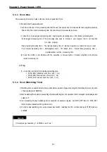
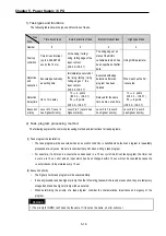
2) Time-driven operation
In time driven interrupt operation method, operations are processed not repeatedly but at every preset interval. In the GM7U
series, interval time can be set between 0.001 to 4,294,967.29 sec. This operation is used to process operation with a
constant cycle.
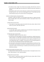
3) Interrupt task operation
The existing PLC program can be interrupted if an operation is required to be urgently processed.
The signal which informs the CPU of the urgent conditions is called the interrupt signal. The GM7U CPU has
three kinds of interrupt operation methods. These are internal, external, and high speed counter interrupt signal me
thods.
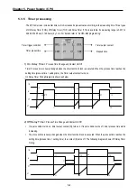
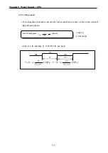
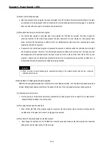
5.3.2 Operation processing at momentary power failure
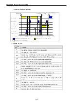
Momentary power failure occurs when the input voltage to the power supply falls below the rated voltage. If there
is momentary power failure under 10ms, the CPU maintains operation processing. If it exceeds 10ms, the CPU will stop
processing and all outputs will be turned off. When the power is restored, the operation will be executed again
automatically.
1) Momentary power failure under 10 ms
2) Momentary power failure exceeding 10 ms
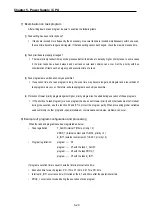
REMARK
1) Momentary power failure?
The PLC defines power failure as a state when the voltage has been lowered over the allowable range. The power
failure with a short interval (several to tens ms) is called momentary power failure.
Momentary power failure
under 1Oms
Power
Input
Power failure exceeding 10m
y
The operation is stopped.
y
The operation is executed again when the
power is restored
y
The operation is maintained.
Power
Input
Содержание GLOFA G7M-DR20U
Страница 28: ...Chapter 4 Names of Parts 4 3 2 G7M DRT60U N 3 G7M DT60U N 4 G7M DT60U P...
Страница 29: ...Chapter 4 Names of Parts 4 4 5 G7M DR60U DC 6 G7M DRT60U N DC 7 G7M DT60U N DC...
Страница 30: ...Chapter 4 Names of Parts 4 5 8 G7M DT60U P DC 4 1 2 40 point main unit 1 G7M DR40U 2 G7M DRT40U N...
Страница 31: ...Chapter 4 Names of Parts 4 6 3 G7M DT40U N 4 G7M DT40U P 5 G7M DR40U DC...
Страница 32: ...Chapter 4 Names of Parts 4 7 6 G7M DRT40U N DC 7 G7M DT40U N DC 8 G7M DT40U P DC...
Страница 33: ...Chapter 4 Names of Parts 4 8 4 1 3 30 point main unit 1 G7M DR30U 2 G7M DRT30U N 3 G7M DT30U N...
Страница 34: ...Chapter 4 Names of Parts 4 9 4 G7M DT30U P 5 G7M DR30U DC 6 G7M DRT30U N DC...
Страница 35: ...Chapter 4 Names of Parts 4 10 7 G7M DT30U N DC 8 G7M DT30U P DC 4 1 4 20 point main unit 1 G7M DR20U...
Страница 36: ...Chapter 4 Names of Parts 4 11 2 G7M DRT20U N 3 G7M DT20U N 4 G7M DT20U P...
Страница 37: ...Chapter 4 Names of Parts 4 12 5 G7M DR20U DC 6 G7M DRT20U N DC 7 G7M DT20U N DC...
Страница 38: ...Chapter 4 Names of Parts 4 13 8 G7M DT20U P DC...
Страница 159: ...Chapter 7 Usage of Various Functions 7 52 c Program...
Страница 183: ...Chapter 7 Usage of Various Functions 7 76 c Program...
Страница 253: ...Chapter 8 Communication Functions 8 27 b When uses Ch 1 Built in RS 485...
Страница 355: ...Appendix 1 System Definitions App1 8 5 PID parameters 1 PID Auto Tuning Parameter 2 PID Parameter...
Страница 356: ...Appendix 1 System Definitions App1 9 6 Position Parameter...
Страница 357: ...Appendix 1 System Definitions App1 10 7 High Speed Counter Parameter...

