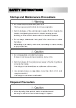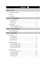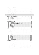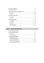
SAFETY INSTRUCTIONS
Design Precautions
Install a safety circuit external to the PLC that keeps the entire system
safe even when there are problems with the external power supply or
the PLC module. Otherwise, serious problems such as erroneous
outputs or operations may occur.
-
Outside the PLC, construct mechanical damage preventing interlock
circuits. These include emergency stop, protective circuits, positioning
upper and lower limits switches and interlocking forward/reverse
operation.
When the PLC detects watchdog timer error, module interface error, or
other hardware errors, it will stop calculation and turn off all output.
However, one or more outputs could be turned on when there are
problems that the PLC CPU cannot detect, such as malfunction of output
device (relay, transistor, etc.) themselves or I/O controller. Build a fail
safe circuit exterior to the PLC to insure the equipment operates safely at
such times. Also, build an external monitoring circuit to monitor any
single outputs that could cause serious problems.
Make sure all external loads connected to output does NOT exceed
the rating of the output module.
Over current exceeding the rating of the output module could cause fire,
damage or malfunction.
Build a circuit that turns on the external power supply when the PLC
main module power is turned on.
If the external power supply is turned on first, it could cause an erroneous
output or operation.
Warning
Содержание GLOFA G7M-DR20U
Страница 28: ...Chapter 4 Names of Parts 4 3 2 G7M DRT60U N 3 G7M DT60U N 4 G7M DT60U P...
Страница 29: ...Chapter 4 Names of Parts 4 4 5 G7M DR60U DC 6 G7M DRT60U N DC 7 G7M DT60U N DC...
Страница 30: ...Chapter 4 Names of Parts 4 5 8 G7M DT60U P DC 4 1 2 40 point main unit 1 G7M DR40U 2 G7M DRT40U N...
Страница 31: ...Chapter 4 Names of Parts 4 6 3 G7M DT40U N 4 G7M DT40U P 5 G7M DR40U DC...
Страница 32: ...Chapter 4 Names of Parts 4 7 6 G7M DRT40U N DC 7 G7M DT40U N DC 8 G7M DT40U P DC...
Страница 33: ...Chapter 4 Names of Parts 4 8 4 1 3 30 point main unit 1 G7M DR30U 2 G7M DRT30U N 3 G7M DT30U N...
Страница 34: ...Chapter 4 Names of Parts 4 9 4 G7M DT30U P 5 G7M DR30U DC 6 G7M DRT30U N DC...
Страница 35: ...Chapter 4 Names of Parts 4 10 7 G7M DT30U N DC 8 G7M DT30U P DC 4 1 4 20 point main unit 1 G7M DR20U...
Страница 36: ...Chapter 4 Names of Parts 4 11 2 G7M DRT20U N 3 G7M DT20U N 4 G7M DT20U P...
Страница 37: ...Chapter 4 Names of Parts 4 12 5 G7M DR20U DC 6 G7M DRT20U N DC 7 G7M DT20U N DC...
Страница 38: ...Chapter 4 Names of Parts 4 13 8 G7M DT20U P DC...
Страница 159: ...Chapter 7 Usage of Various Functions 7 52 c Program...
Страница 183: ...Chapter 7 Usage of Various Functions 7 76 c Program...
Страница 253: ...Chapter 8 Communication Functions 8 27 b When uses Ch 1 Built in RS 485...
Страница 355: ...Appendix 1 System Definitions App1 8 5 PID parameters 1 PID Auto Tuning Parameter 2 PID Parameter...
Страница 356: ...Appendix 1 System Definitions App1 9 6 Position Parameter...
Страница 357: ...Appendix 1 System Definitions App1 10 7 High Speed Counter Parameter...


