


Chapter 8. Communication Functions
8-50
•
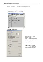
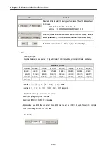
The communication status is saved in the COM_STAT value, and its type is USINT.
•
NDR: When transfer is completed normally, this bit turns on during 1 scan.
•
ERR: When communication error occurs, ,this bit turns on.
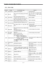
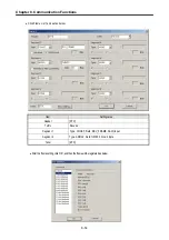
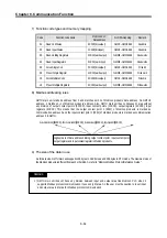
(3) Error code
Code Error
type
Description
06
Slave Device Busy
It’s sending or waiting to receive
09
Parameter Error
Communication parameter setting error, Link enable setting error
10
Frame Type Error
Frame does not setting or frame does not ‘sending’
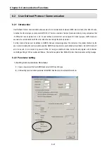
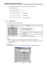
8.2.4 Example
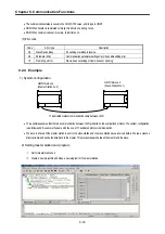
1) System configuration
•
This example assumes that there’s a communication between LSIS’ products by the user-defined protocol. The system configuration
is as follows and the cable is the same with the one of 1:1 dedicated protocol communication.
•
The data in M area of the master station is sent to the slave station and the slave station saves received data in M area, output as
direct variable, and sends the data back to the master. This process repeats between the master and the slave.
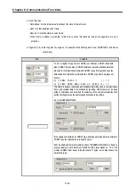
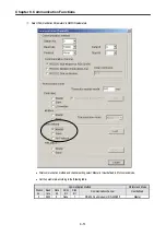
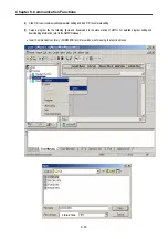
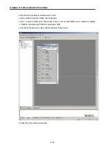
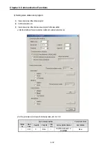
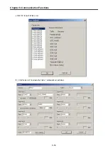
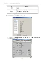
2) Setting master station and program
①
Set for master station no.0
②
Create a new project file and make a new program for the master station.
GM7U main unit
(Slave: Station No. 1)
GM7U main unit
(Master: Station no. 0)
1:1 dedicated protocol communication cable between LSIS’
Содержание GLOFA G7M-DR20U
Страница 28: ...Chapter 4 Names of Parts 4 3 2 G7M DRT60U N 3 G7M DT60U N 4 G7M DT60U P...
Страница 29: ...Chapter 4 Names of Parts 4 4 5 G7M DR60U DC 6 G7M DRT60U N DC 7 G7M DT60U N DC...
Страница 30: ...Chapter 4 Names of Parts 4 5 8 G7M DT60U P DC 4 1 2 40 point main unit 1 G7M DR40U 2 G7M DRT40U N...
Страница 31: ...Chapter 4 Names of Parts 4 6 3 G7M DT40U N 4 G7M DT40U P 5 G7M DR40U DC...
Страница 32: ...Chapter 4 Names of Parts 4 7 6 G7M DRT40U N DC 7 G7M DT40U N DC 8 G7M DT40U P DC...
Страница 33: ...Chapter 4 Names of Parts 4 8 4 1 3 30 point main unit 1 G7M DR30U 2 G7M DRT30U N 3 G7M DT30U N...
Страница 34: ...Chapter 4 Names of Parts 4 9 4 G7M DT30U P 5 G7M DR30U DC 6 G7M DRT30U N DC...
Страница 35: ...Chapter 4 Names of Parts 4 10 7 G7M DT30U N DC 8 G7M DT30U P DC 4 1 4 20 point main unit 1 G7M DR20U...
Страница 36: ...Chapter 4 Names of Parts 4 11 2 G7M DRT20U N 3 G7M DT20U N 4 G7M DT20U P...
Страница 37: ...Chapter 4 Names of Parts 4 12 5 G7M DR20U DC 6 G7M DRT20U N DC 7 G7M DT20U N DC...
Страница 38: ...Chapter 4 Names of Parts 4 13 8 G7M DT20U P DC...
Страница 159: ...Chapter 7 Usage of Various Functions 7 52 c Program...
Страница 183: ...Chapter 7 Usage of Various Functions 7 76 c Program...
Страница 253: ...Chapter 8 Communication Functions 8 27 b When uses Ch 1 Built in RS 485...
Страница 355: ...Appendix 1 System Definitions App1 8 5 PID parameters 1 PID Auto Tuning Parameter 2 PID Parameter...
Страница 356: ...Appendix 1 System Definitions App1 9 6 Position Parameter...
Страница 357: ...Appendix 1 System Definitions App1 10 7 High Speed Counter Parameter...


