


Chapter 5. Power Supply / CPU
5-26
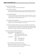
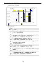
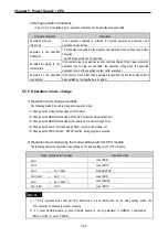
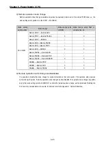
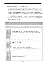
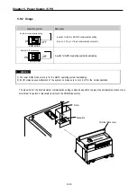
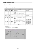
3) Remote operation mode change
Remote operation mode change is available only when the operation mode is set to the remote STOP mode (i.e., the
mode setting switch position is in the STOP
→
PAU/REM’).
Mode setting
switch position
Mode Change
Mode change by the
GMWIN
Mode change using FAM or
computer link, etc.
Remote STOP
→
Remote RUN
○
○
Remote STOP
→
Remote PAUSE
X
X
Remote STOP
→
DEBUG
○
○
Remote RUN
→
Remote PAUSE
○
○
Remote RUN
→
Remote STOP
○
○
Remote RUN
→
DEBUG
X
X
Remote PAUSE
→
Remote RUN
○
○
Remote PAUSE
→
Remote STOP
○
○
Remote PAUSE
→
Remote DEBUG
X
X
DEBUG
→
Remote STOP
○
○
DEBUG
→
Remote RUN
X
X
PAU / REM
DEBUG
→
Remote PAUSE
X
X
4) Remote operation mode change enable/disable
It is possible to disable the mode change for system protection so that some parts of the operation mode sources
cannot change the mode. If remote operation mode change has been disabled, the operation mode change is possible
only by the mode setting switch and GMWIN. To enable the remote operation change, set the parameter ‘Enabling the
PLC control by communications’ to enable. (For details, refer to the Appendix 1. System Definitions)
Содержание GLOFA G7M-DR20U
Страница 28: ...Chapter 4 Names of Parts 4 3 2 G7M DRT60U N 3 G7M DT60U N 4 G7M DT60U P...
Страница 29: ...Chapter 4 Names of Parts 4 4 5 G7M DR60U DC 6 G7M DRT60U N DC 7 G7M DT60U N DC...
Страница 30: ...Chapter 4 Names of Parts 4 5 8 G7M DT60U P DC 4 1 2 40 point main unit 1 G7M DR40U 2 G7M DRT40U N...
Страница 31: ...Chapter 4 Names of Parts 4 6 3 G7M DT40U N 4 G7M DT40U P 5 G7M DR40U DC...
Страница 32: ...Chapter 4 Names of Parts 4 7 6 G7M DRT40U N DC 7 G7M DT40U N DC 8 G7M DT40U P DC...
Страница 33: ...Chapter 4 Names of Parts 4 8 4 1 3 30 point main unit 1 G7M DR30U 2 G7M DRT30U N 3 G7M DT30U N...
Страница 34: ...Chapter 4 Names of Parts 4 9 4 G7M DT30U P 5 G7M DR30U DC 6 G7M DRT30U N DC...
Страница 35: ...Chapter 4 Names of Parts 4 10 7 G7M DT30U N DC 8 G7M DT30U P DC 4 1 4 20 point main unit 1 G7M DR20U...
Страница 36: ...Chapter 4 Names of Parts 4 11 2 G7M DRT20U N 3 G7M DT20U N 4 G7M DT20U P...
Страница 37: ...Chapter 4 Names of Parts 4 12 5 G7M DR20U DC 6 G7M DRT20U N DC 7 G7M DT20U N DC...
Страница 38: ...Chapter 4 Names of Parts 4 13 8 G7M DT20U P DC...
Страница 159: ...Chapter 7 Usage of Various Functions 7 52 c Program...
Страница 183: ...Chapter 7 Usage of Various Functions 7 76 c Program...
Страница 253: ...Chapter 8 Communication Functions 8 27 b When uses Ch 1 Built in RS 485...
Страница 355: ...Appendix 1 System Definitions App1 8 5 PID parameters 1 PID Auto Tuning Parameter 2 PID Parameter...
Страница 356: ...Appendix 1 System Definitions App1 9 6 Position Parameter...
Страница 357: ...Appendix 1 System Definitions App1 10 7 High Speed Counter Parameter...


