


Chapter 5. Power Supply / CPU
5-7
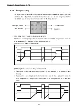
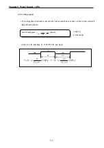
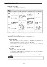
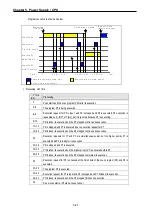
5.3.3 Scan time
The processing time from a 0 step to the next 0 step is called Scan Time.
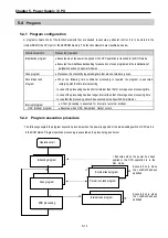
1) Scan time measurement
Scan time is the sum of the processing time that the user has written, and this includes the task program processing
time and the PLC internal processing time. The scan time can be measured as below.
(1) Scan time = Scan program processing time + Task program processing time + PLC internal processing time
• Scan program processing time = The processing time used to process a user program that is not specified
to a task program.
• Task program processing time = The total processing time of interrupt programs executed during one scan.
• PLC internal processing time = Self-diagnosis time + I/O refresh time + Internal data processing time +
Communications service processing time
(2) Scan time differs in accordance with the execution or non-execution of interrupt programs and commun
ication processing, etc.
2) Flag
(1)
Scan time is stored in the following system flag area.
y
_SCAN_MAX: Maximum scan time (unit: 1 ms)
y
_SCAN_MIN: Minimum scan time (unit: 1 ms)
y
_SCAN_CUR: Current scan time (unit: 1 ms)
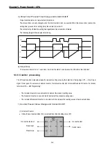
5.3.4 Scan Watchdog Timer
1) Watchdog timer is used to detect a delay of abnormal operation of sequence program (Watchdog time is set in menu
of basic parameter of GMWIN.)
2) When watchdog timer detects an exceeding of preset watchdog time, the operation of PLC is stopped immediately and all
output is off.
3) If an exceeding of preset watchdog time is expected in sequence program, use ‘WDT_RST’ function. ‘WDT_RST’
function makes elapsed watchdog time as zero.
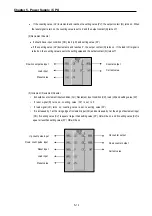
4) In order to clear watchdog error, using manual reset switch, restarting the PLC or mode change to STOP mode are
available.
REMARK
1) Setting range of watchdog: 1 ~ 65535ms ( unit: 1ms ).
Содержание GLOFA G7M-DR20U
Страница 28: ...Chapter 4 Names of Parts 4 3 2 G7M DRT60U N 3 G7M DT60U N 4 G7M DT60U P...
Страница 29: ...Chapter 4 Names of Parts 4 4 5 G7M DR60U DC 6 G7M DRT60U N DC 7 G7M DT60U N DC...
Страница 30: ...Chapter 4 Names of Parts 4 5 8 G7M DT60U P DC 4 1 2 40 point main unit 1 G7M DR40U 2 G7M DRT40U N...
Страница 31: ...Chapter 4 Names of Parts 4 6 3 G7M DT40U N 4 G7M DT40U P 5 G7M DR40U DC...
Страница 32: ...Chapter 4 Names of Parts 4 7 6 G7M DRT40U N DC 7 G7M DT40U N DC 8 G7M DT40U P DC...
Страница 33: ...Chapter 4 Names of Parts 4 8 4 1 3 30 point main unit 1 G7M DR30U 2 G7M DRT30U N 3 G7M DT30U N...
Страница 34: ...Chapter 4 Names of Parts 4 9 4 G7M DT30U P 5 G7M DR30U DC 6 G7M DRT30U N DC...
Страница 35: ...Chapter 4 Names of Parts 4 10 7 G7M DT30U N DC 8 G7M DT30U P DC 4 1 4 20 point main unit 1 G7M DR20U...
Страница 36: ...Chapter 4 Names of Parts 4 11 2 G7M DRT20U N 3 G7M DT20U N 4 G7M DT20U P...
Страница 37: ...Chapter 4 Names of Parts 4 12 5 G7M DR20U DC 6 G7M DRT20U N DC 7 G7M DT20U N DC...
Страница 38: ...Chapter 4 Names of Parts 4 13 8 G7M DT20U P DC...
Страница 159: ...Chapter 7 Usage of Various Functions 7 52 c Program...
Страница 183: ...Chapter 7 Usage of Various Functions 7 76 c Program...
Страница 253: ...Chapter 8 Communication Functions 8 27 b When uses Ch 1 Built in RS 485...
Страница 355: ...Appendix 1 System Definitions App1 8 5 PID parameters 1 PID Auto Tuning Parameter 2 PID Parameter...
Страница 356: ...Appendix 1 System Definitions App1 9 6 Position Parameter...
Страница 357: ...Appendix 1 System Definitions App1 10 7 High Speed Counter Parameter...


