


Chapter 11. Troubleshooting
11-1
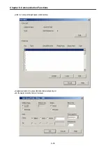
Chapter 11. Troubleshooting
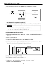
The following explains contents, diagnosis and corrective actions for various errors that can occur during system operation.
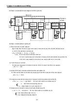
11.1 Basic Procedures of Troubleshooting
System reliability not only depends on reliable equipment but also on short downtimes in the event of faults. The
short discovery and corrective action is needed for speedy operation of system. The following shows the basic i
nstructions for troubleshooting
.
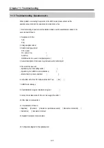
1) Visual checks
Check the following points.
• Machine operating condition (in stop and operating status)
• Power On/Off
• Status of I/O devices
• Condition of wiring (I/O wires, extension and communications cables)
• Display states of various indicators (such as POWER LED, RUN LED, ERR. LED and I/O LED).
After checking them, connect peripheral devices and check the operation status of the PLC and the
program contents.
2) Trouble check
Observe any change in the error conditions during the following.
• Switch to the STOP, and then turn the power on and off.
3) Narrow down the possible causes of the trouble, i.e.:
• Inside or outside of the PLC?
• I/O module or another module?
• PLC program?
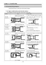
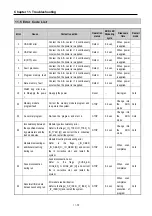
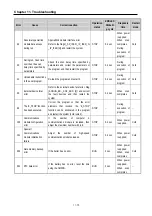
11.2 Troubleshooting
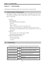
This section explains the procedure for determining the cause of troubles as well as the errors and corrective actions.
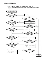
Is the power LED turned OFF?
Flowchart used when the POWER LED is turned OFF
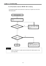
Is the ERR LED flickering
?
Flowchart used when the ERR LED is flickering
Are the RUN LED turned OFF?
Flowchart used when the RUN turned OFF.
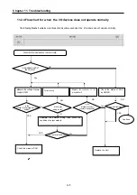
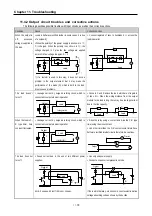
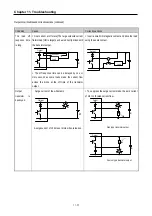
I/O module doesn’t operate pro
perly
Flowchart used when the output load of the output module
doesn’t turn on.
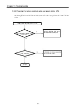
Program cannot be written
Flowchart used when a program can’t be written to the PLC
Содержание GLOFA G7M-DR20U
Страница 28: ...Chapter 4 Names of Parts 4 3 2 G7M DRT60U N 3 G7M DT60U N 4 G7M DT60U P...
Страница 29: ...Chapter 4 Names of Parts 4 4 5 G7M DR60U DC 6 G7M DRT60U N DC 7 G7M DT60U N DC...
Страница 30: ...Chapter 4 Names of Parts 4 5 8 G7M DT60U P DC 4 1 2 40 point main unit 1 G7M DR40U 2 G7M DRT40U N...
Страница 31: ...Chapter 4 Names of Parts 4 6 3 G7M DT40U N 4 G7M DT40U P 5 G7M DR40U DC...
Страница 32: ...Chapter 4 Names of Parts 4 7 6 G7M DRT40U N DC 7 G7M DT40U N DC 8 G7M DT40U P DC...
Страница 33: ...Chapter 4 Names of Parts 4 8 4 1 3 30 point main unit 1 G7M DR30U 2 G7M DRT30U N 3 G7M DT30U N...
Страница 34: ...Chapter 4 Names of Parts 4 9 4 G7M DT30U P 5 G7M DR30U DC 6 G7M DRT30U N DC...
Страница 35: ...Chapter 4 Names of Parts 4 10 7 G7M DT30U N DC 8 G7M DT30U P DC 4 1 4 20 point main unit 1 G7M DR20U...
Страница 36: ...Chapter 4 Names of Parts 4 11 2 G7M DRT20U N 3 G7M DT20U N 4 G7M DT20U P...
Страница 37: ...Chapter 4 Names of Parts 4 12 5 G7M DR20U DC 6 G7M DRT20U N DC 7 G7M DT20U N DC...
Страница 38: ...Chapter 4 Names of Parts 4 13 8 G7M DT20U P DC...
Страница 159: ...Chapter 7 Usage of Various Functions 7 52 c Program...
Страница 183: ...Chapter 7 Usage of Various Functions 7 76 c Program...
Страница 253: ...Chapter 8 Communication Functions 8 27 b When uses Ch 1 Built in RS 485...
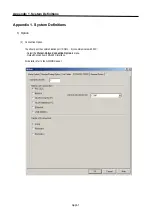
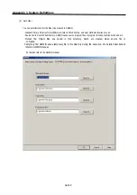
Страница 355: ...Appendix 1 System Definitions App1 8 5 PID parameters 1 PID Auto Tuning Parameter 2 PID Parameter...
Страница 356: ...Appendix 1 System Definitions App1 9 6 Position Parameter...
Страница 357: ...Appendix 1 System Definitions App1 10 7 High Speed Counter Parameter...


