


Chapter 5. Power Supply / CPU
5-29
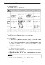
5.6.2 Self-diagnosis
1) Functions
(1) The self-diagnosis function permits the CPU module to detect its own errors.
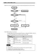
(2) Self-diagnosis is carried out when the PLC power supply is turned on and when an error occurs the PLC is in the
RUN state. If an error is detected, the system stops operation to prevent faulty PLC operation.
2) Error flag
If an error occurs, it will be stored to the following flags and the STOP LED flickers.
• Representative system error flag: _CNT_ER
• Representative system warning flag: _CNF_WAR
REMARK
1) Refer to 11.5 ‘Error Code List of Chapter 11’. Troubleshooting for details of contents of self-diagnosis
and corrective actions.
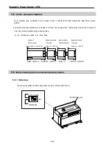
5.6.3 Remote function
The CPU module can be controlled by external operations (from GMWIN and computer link module, etc.). For remote
operation, set the mode setting switch of CPU module to remote position.
1) Remote RUN/STOP
(1) The remote RUN/STOP permits external operations to RUN/STOP the CPU module under the condition that the
mode- selling switch of CPU module is in the remote position.
(2) This function is convenient when the CPU module is located on the place where it is difficult to control the CPU
module or the user want to control the CPU module in the control panel from outside.
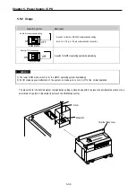
2) Remote PAUSE
(1) The remote PAUSE permits external operations to execute PAUSE operations under the condition that the mode-
setting switch of CPU module is in the remote position. The PAUSE operations stop the CPU module operation
processing while maintaining the On/Off state of the output module.
(2) This function is convenient when the user wants to maintain the ON state of the output module under the condition
the CPU module has been stopped.
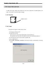
3) Remote DEBUG
(1) This function permits external operations to execute DEBUG operations under the condition that the mode setting
switch of CPU module is in the remote position. The DEBUG operations execute programs complying with the
specified operation conditions.
(2) This function is convenient when program execution or contents of any data are checked for debugging of the
program.
Содержание GLOFA G7M-DR20U
Страница 28: ...Chapter 4 Names of Parts 4 3 2 G7M DRT60U N 3 G7M DT60U N 4 G7M DT60U P...
Страница 29: ...Chapter 4 Names of Parts 4 4 5 G7M DR60U DC 6 G7M DRT60U N DC 7 G7M DT60U N DC...
Страница 30: ...Chapter 4 Names of Parts 4 5 8 G7M DT60U P DC 4 1 2 40 point main unit 1 G7M DR40U 2 G7M DRT40U N...
Страница 31: ...Chapter 4 Names of Parts 4 6 3 G7M DT40U N 4 G7M DT40U P 5 G7M DR40U DC...
Страница 32: ...Chapter 4 Names of Parts 4 7 6 G7M DRT40U N DC 7 G7M DT40U N DC 8 G7M DT40U P DC...
Страница 33: ...Chapter 4 Names of Parts 4 8 4 1 3 30 point main unit 1 G7M DR30U 2 G7M DRT30U N 3 G7M DT30U N...
Страница 34: ...Chapter 4 Names of Parts 4 9 4 G7M DT30U P 5 G7M DR30U DC 6 G7M DRT30U N DC...
Страница 35: ...Chapter 4 Names of Parts 4 10 7 G7M DT30U N DC 8 G7M DT30U P DC 4 1 4 20 point main unit 1 G7M DR20U...
Страница 36: ...Chapter 4 Names of Parts 4 11 2 G7M DRT20U N 3 G7M DT20U N 4 G7M DT20U P...
Страница 37: ...Chapter 4 Names of Parts 4 12 5 G7M DR20U DC 6 G7M DRT20U N DC 7 G7M DT20U N DC...
Страница 38: ...Chapter 4 Names of Parts 4 13 8 G7M DT20U P DC...
Страница 159: ...Chapter 7 Usage of Various Functions 7 52 c Program...
Страница 183: ...Chapter 7 Usage of Various Functions 7 76 c Program...
Страница 253: ...Chapter 8 Communication Functions 8 27 b When uses Ch 1 Built in RS 485...
Страница 355: ...Appendix 1 System Definitions App1 8 5 PID parameters 1 PID Auto Tuning Parameter 2 PID Parameter...
Страница 356: ...Appendix 1 System Definitions App1 9 6 Position Parameter...
Страница 357: ...Appendix 1 System Definitions App1 10 7 High Speed Counter Parameter...


