


Chapter 7. Usage of Various Functions
7-74
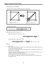
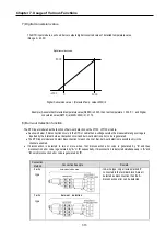
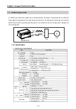
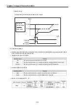
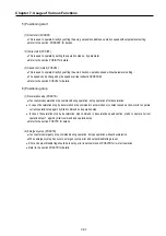
4-wire
type
No wiring
*1 : Pt
*2: Shield wire
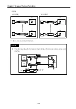
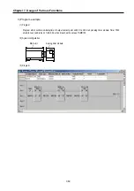
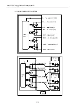
9) Wiring
(1)
Caution for wiring
•
Make sure that external input signal of the mixture module of AC and analog I/O is not affected by induction noise or occurs
from the AC through using another cable.
•
Wire is adopted with consideration about peripheral temperature and electric current allowance. Thicker than Max. size of
wire AWG22 (0.3
㎟
) is better.
•
If wire is put near to high temp. radiated device or contacted with oil for a long time, it may cause of electric leakage so that it
gets broken or miss-operation during wiring.
•
Be sure to connect with care of polarity while connecting to external 24V DC power supply.
•
In case of wiring with high voltage line or generation line, it makes induction failure so then it may cause of miss-operation
and out of order.
(2)
Wiring example
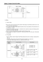
•
Number of method of connection between Pt and RTD input module are three, that is, 2-wired type, 3-wired type and 4-w
wired type.
•
The resistance of the wires used to connect Pt to RTD input module should be 10
Ω
or less per wire.
The same wire (in thickness, length, and kind, etc.) should be used for each channel.
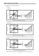
Connection
Method
Connection Example
Wire Conditions
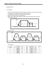
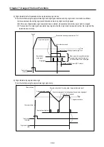
2-wired type
3-wired type
ℵ
wire resistance
≤
10
Ω
ℑ
wire resistance
≤
10
Ω
ℜ
wire resistance
≤
10
Ω
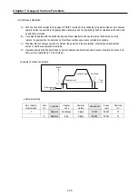
The difference between the resistance values
of the wires
①
and
②
: 1
Ω
or less
The difference between the resistance values
of the wires
②
and
③
: 1
Ω
or less
The difference between the resistance values
of the wires
③
and
①
: 1
Ω
or less
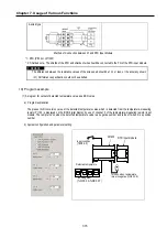
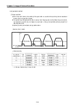
burn-out detection
Содержание GLOFA G7M-DR20U
Страница 28: ...Chapter 4 Names of Parts 4 3 2 G7M DRT60U N 3 G7M DT60U N 4 G7M DT60U P...
Страница 29: ...Chapter 4 Names of Parts 4 4 5 G7M DR60U DC 6 G7M DRT60U N DC 7 G7M DT60U N DC...
Страница 30: ...Chapter 4 Names of Parts 4 5 8 G7M DT60U P DC 4 1 2 40 point main unit 1 G7M DR40U 2 G7M DRT40U N...
Страница 31: ...Chapter 4 Names of Parts 4 6 3 G7M DT40U N 4 G7M DT40U P 5 G7M DR40U DC...
Страница 32: ...Chapter 4 Names of Parts 4 7 6 G7M DRT40U N DC 7 G7M DT40U N DC 8 G7M DT40U P DC...
Страница 33: ...Chapter 4 Names of Parts 4 8 4 1 3 30 point main unit 1 G7M DR30U 2 G7M DRT30U N 3 G7M DT30U N...
Страница 34: ...Chapter 4 Names of Parts 4 9 4 G7M DT30U P 5 G7M DR30U DC 6 G7M DRT30U N DC...
Страница 35: ...Chapter 4 Names of Parts 4 10 7 G7M DT30U N DC 8 G7M DT30U P DC 4 1 4 20 point main unit 1 G7M DR20U...
Страница 36: ...Chapter 4 Names of Parts 4 11 2 G7M DRT20U N 3 G7M DT20U N 4 G7M DT20U P...
Страница 37: ...Chapter 4 Names of Parts 4 12 5 G7M DR20U DC 6 G7M DRT20U N DC 7 G7M DT20U N DC...
Страница 38: ...Chapter 4 Names of Parts 4 13 8 G7M DT20U P DC...
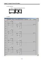
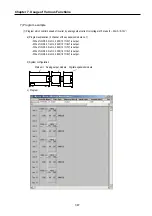
Страница 159: ...Chapter 7 Usage of Various Functions 7 52 c Program...
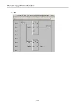
Страница 183: ...Chapter 7 Usage of Various Functions 7 76 c Program...
Страница 253: ...Chapter 8 Communication Functions 8 27 b When uses Ch 1 Built in RS 485...
Страница 355: ...Appendix 1 System Definitions App1 8 5 PID parameters 1 PID Auto Tuning Parameter 2 PID Parameter...
Страница 356: ...Appendix 1 System Definitions App1 9 6 Position Parameter...
Страница 357: ...Appendix 1 System Definitions App1 10 7 High Speed Counter Parameter...


