Chapter 5. Power Supply / CPU
5-5
5.3
Operation Processing
5.3.1 Operation method
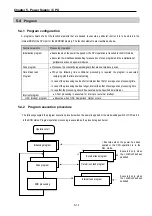
1) Cyclic execution
A PLC program is sequentially executed from the first step to the last step. This process is called a scan, and the
sequential processing is called cyclic execution. Cyclic execution of the PLC continues as long as the conditions
are not changed for the interrupt processing during program execution. This processing is classified into the following
stages:
Stages
Processing
Operation Start
Initialization
Input image area refresh
Program operation processing
Program starts
~
Program ends
Input/Output image area refresh
END processing
Stage for the start of a scan processing. It is executed only
one time when the power is applied or reset is executed.
It executes the following process:
▶
I/O reset
▶
Execution of self-diagnosis
▶
Data clear
▶
Allocating I/O address and type
Program is sequentially executed from the first step to the last
step.
The contents stored in the output image area is output to output
part when operation processing of a program is finished.
Input conditions are read and stored into the input image
area before starting process.
Stage for return processing after the CPU part has finished
1 scan. The END processing following process is executed.
▶
Self-diagnosis
▶
Change the present values of the timer and counter, etc.
▶
Processing data communications between the computer
link and communications module.
▶
Checking the switch for mode settings.
Содержание GLOFA G7M-DR20U
Страница 28: ...Chapter 4 Names of Parts 4 3 2 G7M DRT60U N 3 G7M DT60U N 4 G7M DT60U P...
Страница 29: ...Chapter 4 Names of Parts 4 4 5 G7M DR60U DC 6 G7M DRT60U N DC 7 G7M DT60U N DC...
Страница 30: ...Chapter 4 Names of Parts 4 5 8 G7M DT60U P DC 4 1 2 40 point main unit 1 G7M DR40U 2 G7M DRT40U N...
Страница 31: ...Chapter 4 Names of Parts 4 6 3 G7M DT40U N 4 G7M DT40U P 5 G7M DR40U DC...
Страница 32: ...Chapter 4 Names of Parts 4 7 6 G7M DRT40U N DC 7 G7M DT40U N DC 8 G7M DT40U P DC...
Страница 33: ...Chapter 4 Names of Parts 4 8 4 1 3 30 point main unit 1 G7M DR30U 2 G7M DRT30U N 3 G7M DT30U N...
Страница 34: ...Chapter 4 Names of Parts 4 9 4 G7M DT30U P 5 G7M DR30U DC 6 G7M DRT30U N DC...
Страница 35: ...Chapter 4 Names of Parts 4 10 7 G7M DT30U N DC 8 G7M DT30U P DC 4 1 4 20 point main unit 1 G7M DR20U...
Страница 36: ...Chapter 4 Names of Parts 4 11 2 G7M DRT20U N 3 G7M DT20U N 4 G7M DT20U P...
Страница 37: ...Chapter 4 Names of Parts 4 12 5 G7M DR20U DC 6 G7M DRT20U N DC 7 G7M DT20U N DC...
Страница 38: ...Chapter 4 Names of Parts 4 13 8 G7M DT20U P DC...
Страница 159: ...Chapter 7 Usage of Various Functions 7 52 c Program...
Страница 183: ...Chapter 7 Usage of Various Functions 7 76 c Program...
Страница 253: ...Chapter 8 Communication Functions 8 27 b When uses Ch 1 Built in RS 485...
Страница 355: ...Appendix 1 System Definitions App1 8 5 PID parameters 1 PID Auto Tuning Parameter 2 PID Parameter...
Страница 356: ...Appendix 1 System Definitions App1 9 6 Position Parameter...
Страница 357: ...Appendix 1 System Definitions App1 10 7 High Speed Counter Parameter...

