


Chapter 8. Communication Functions
8-48
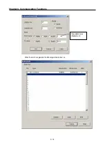
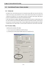
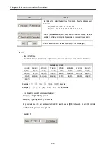
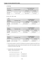
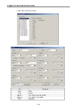
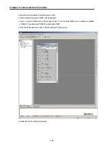
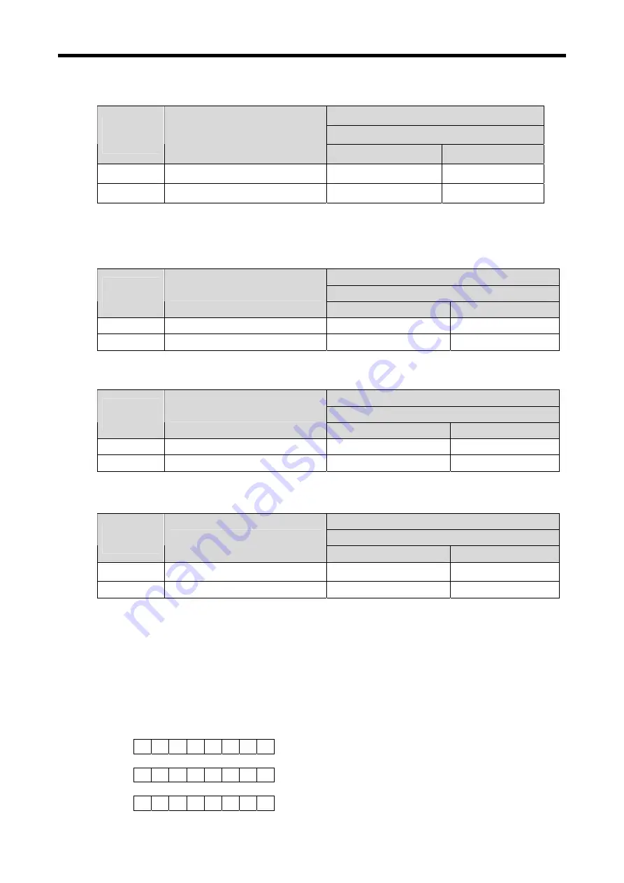
(1) Default setting
The last transmitting frame
BCC Type setting
The kinds of
Input segment
The value of sum check
ASCII Type
Hex Type
ASCII Input
31 + 32 + 33 + 34 + 04 =
CE
05 31 32 33 34 04 43 45
05 31 32 33 34 04 CE
Hex Input
12 + 34 + 04 =
4A
05 12 34 04 34 41
05 12 34 04 4A
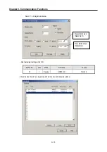
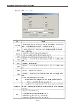
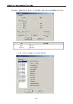
(2) SUM 1, XOR 1 or MUL 1 setting.
①
SUM 1
The last transmitting frame
BCC Type setting
The kinds of
segment input
The value of sum check
ASCII Type
Hex Type
ASCII Input
05 + 31 + 32 + 33 + 34 + 04 =
D3
05 31 32 33 34 04 44 33
05 31 32 33 34 04 D3
Hex Input
05 + 12 + 34 + 04 =
4F
05 12 34 04 34 46
05 12 34 04 4F
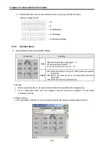
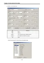
②
XOR 1
The last transmitting frame
BCC Type setting
The kinds of
segment input
The value of sum check
ASCII Type
Hex Type
ASCII Input
05 ^ 31 ^ 32 ^ 33 ^ 34 ^ 04 =
05
05 31 32 33 34 04 30 35
05 31 32 33 34 04 05
Hex Input
05 ^ 12 ^ 34 ^ 04 = 27
05 12 34 04 32 37
05 12 34 04 27
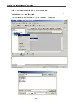
③
MUL 1
The last transmitting frame
BCC Type setting
The kinds of
segment input
The value of sum check
ASCII Type
Hex Type
ASCII Input
05 * 31 * 32 * 33 * 34 * 04 =
60
05 31 32 33 34 04 36 30
05 31 32 33 34 04 60
Hex Input
05 * 12 * 34 * 04 =
20
05 12 34 04 32 30
05 12 34 04 20
④
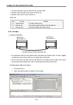
LRC and CRC check BCC in the same error check method which is provided in the modbus protocol. CRC is used in
the HEX communication, and LRC is used in the ASC communication. However, LRC is only used when the number
of data is an even number in the check range.
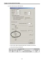
⑤
Complement setting : Complement calculation as below
Example> 1’s and 2’s complements of D3
1 1 0 1 0 0 1 1
0 0 1 0 1 1 0 0
0 0 1 0 1 1 0 1
= 2C (Complements of 1)
= 2D (Complements of 2)
= D3
Содержание GLOFA G7M-DR20U
Страница 28: ...Chapter 4 Names of Parts 4 3 2 G7M DRT60U N 3 G7M DT60U N 4 G7M DT60U P...
Страница 29: ...Chapter 4 Names of Parts 4 4 5 G7M DR60U DC 6 G7M DRT60U N DC 7 G7M DT60U N DC...
Страница 30: ...Chapter 4 Names of Parts 4 5 8 G7M DT60U P DC 4 1 2 40 point main unit 1 G7M DR40U 2 G7M DRT40U N...
Страница 31: ...Chapter 4 Names of Parts 4 6 3 G7M DT40U N 4 G7M DT40U P 5 G7M DR40U DC...
Страница 32: ...Chapter 4 Names of Parts 4 7 6 G7M DRT40U N DC 7 G7M DT40U N DC 8 G7M DT40U P DC...
Страница 33: ...Chapter 4 Names of Parts 4 8 4 1 3 30 point main unit 1 G7M DR30U 2 G7M DRT30U N 3 G7M DT30U N...
Страница 34: ...Chapter 4 Names of Parts 4 9 4 G7M DT30U P 5 G7M DR30U DC 6 G7M DRT30U N DC...
Страница 35: ...Chapter 4 Names of Parts 4 10 7 G7M DT30U N DC 8 G7M DT30U P DC 4 1 4 20 point main unit 1 G7M DR20U...
Страница 36: ...Chapter 4 Names of Parts 4 11 2 G7M DRT20U N 3 G7M DT20U N 4 G7M DT20U P...
Страница 37: ...Chapter 4 Names of Parts 4 12 5 G7M DR20U DC 6 G7M DRT20U N DC 7 G7M DT20U N DC...
Страница 38: ...Chapter 4 Names of Parts 4 13 8 G7M DT20U P DC...
Страница 159: ...Chapter 7 Usage of Various Functions 7 52 c Program...
Страница 183: ...Chapter 7 Usage of Various Functions 7 76 c Program...
Страница 253: ...Chapter 8 Communication Functions 8 27 b When uses Ch 1 Built in RS 485...
Страница 355: ...Appendix 1 System Definitions App1 8 5 PID parameters 1 PID Auto Tuning Parameter 2 PID Parameter...
Страница 356: ...Appendix 1 System Definitions App1 9 6 Position Parameter...
Страница 357: ...Appendix 1 System Definitions App1 10 7 High Speed Counter Parameter...


