Chapter 8. Communication Function
8-63
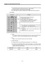
3) Address area
(1)
Setting range is available from 1 to 247, but GM7U supports from 0 to 31.
(2)
Address 0 is used for broadcast address. Broadcast address is all slave devices recognize and respond to
like the self-address, which can't be supported by GM7U.
4) Function code area
(1)
GM7U supports only 01, 02, 03, 04, 05, 06, 15, and 16 among Modicon products' function codes.
(2)
If the response format is (ACK), it uses the same function code.
(3)
If the response format is confirm- (NCK), it returns as it sets the 8th bit of function code as 1.
Ex) If function code is 03, (write only function code part here because only function codes are different.)
[Request]
0000 0011 (16#03)
[]
0000 0011 (16#03)
[Confirm-]
1000 0011 (16#83)
5) Data area
(1)
It sends data, using ASCII data (ASCII mode) or hex (RTU mode).
(2)
Data is changed according to each function code.
(3)
Response frame uses data area as response data or error code.
6) LRC check/CRC check area
(1)
LRC (Longitudinal Redundancy Check): It works in ASCII mode. It takes 2 complement from sum of frame
except header or tail to change into ASCII code,
(2)
CRC (Cyclical Redundancy Check): It works in RTU mode. It uses 2-byte CRC check rules.
It returns as it sets the 8th bit of
function code of request frame.
1)
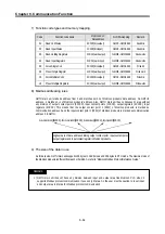
All numerical data can use hexadecimal, decimal, and binary type. If we convert decimal 7 and 10 into each type:
Hexadecimal: 16#07, 16#0A
Decimal: 7, 10
Binary: 2#0111, 2#1010
REMARK
Содержание GLOFA G7M-DR20U
Страница 28: ...Chapter 4 Names of Parts 4 3 2 G7M DRT60U N 3 G7M DT60U N 4 G7M DT60U P...
Страница 29: ...Chapter 4 Names of Parts 4 4 5 G7M DR60U DC 6 G7M DRT60U N DC 7 G7M DT60U N DC...
Страница 30: ...Chapter 4 Names of Parts 4 5 8 G7M DT60U P DC 4 1 2 40 point main unit 1 G7M DR40U 2 G7M DRT40U N...
Страница 31: ...Chapter 4 Names of Parts 4 6 3 G7M DT40U N 4 G7M DT40U P 5 G7M DR40U DC...
Страница 32: ...Chapter 4 Names of Parts 4 7 6 G7M DRT40U N DC 7 G7M DT40U N DC 8 G7M DT40U P DC...
Страница 33: ...Chapter 4 Names of Parts 4 8 4 1 3 30 point main unit 1 G7M DR30U 2 G7M DRT30U N 3 G7M DT30U N...
Страница 34: ...Chapter 4 Names of Parts 4 9 4 G7M DT30U P 5 G7M DR30U DC 6 G7M DRT30U N DC...
Страница 35: ...Chapter 4 Names of Parts 4 10 7 G7M DT30U N DC 8 G7M DT30U P DC 4 1 4 20 point main unit 1 G7M DR20U...
Страница 36: ...Chapter 4 Names of Parts 4 11 2 G7M DRT20U N 3 G7M DT20U N 4 G7M DT20U P...
Страница 37: ...Chapter 4 Names of Parts 4 12 5 G7M DR20U DC 6 G7M DRT20U N DC 7 G7M DT20U N DC...
Страница 38: ...Chapter 4 Names of Parts 4 13 8 G7M DT20U P DC...
Страница 159: ...Chapter 7 Usage of Various Functions 7 52 c Program...
Страница 183: ...Chapter 7 Usage of Various Functions 7 76 c Program...
Страница 253: ...Chapter 8 Communication Functions 8 27 b When uses Ch 1 Built in RS 485...
Страница 355: ...Appendix 1 System Definitions App1 8 5 PID parameters 1 PID Auto Tuning Parameter 2 PID Parameter...
Страница 356: ...Appendix 1 System Definitions App1 9 6 Position Parameter...
Страница 357: ...Appendix 1 System Definitions App1 10 7 High Speed Counter Parameter...

