background image

Chapter 8. Communication Functions 


8-19 


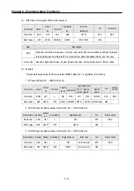
5) 

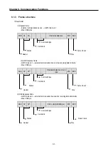
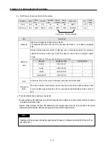
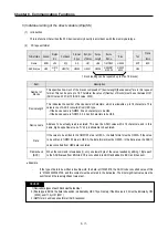
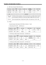
Registering variable for monitoring (X##)


(1)


Introduction 


      Variables separately registered up to 10 (from 0 to 10) in combination with actual variable reading command, and carries 

out the registered one through monitor command after registering. 


(2)


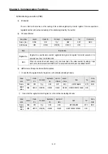
PC request fromat 


Format 

name 

Header  Station 

No. 

Command 

Register 

no. 

Registration format 

Tail 

Frame 

check 

Frame (Ex.) 

ENQ 

H10 

X(x) 

H09 

See register format 

EOT 

BCC 

ASCII value 

H05 

H3130 

H58(78) 

H3039 

[ ]

 H04 


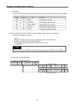
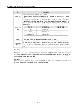
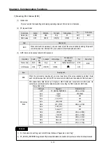
Item 

Description 

BCC 

When the command is lowercase(r), only one lower byte of the value resulted by adding 1 Byte 

each to the ASCII values from ENQ to EOT is converted into ASCII and added to BCC, and then 

sent. 

Register no. 

Up to 10 can be registered (0 to 9, H00-H09). If a registered no. is registered again, only the one 

currently being executed is registered. 

Register 

format 

This is used to before EOT in command; individual reading of direct variable and continuous 

reading format. 


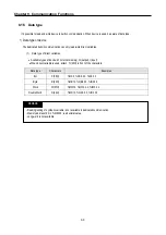
[ ]

: Only one of following can be selected for register format. 


Individual reading of the direct device 


RSS 

Number of blocks (2 Byte) 

Device length (2 Byte) 

Device name (16 Byte) 

... 


           1 block (max. 16 blocks) 


Continuous reading of the direct device 


RSB 

Device length (2 Byte)


Device name (16 Byte)


Number of data 


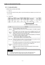
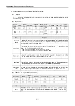
(3)


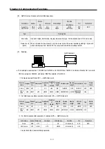
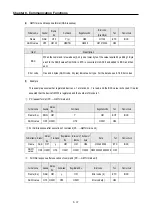
GM7U main unit response format (ACK response) 


Format name 

Header 

Station No. 

Command 

Registration No. 

Tail 

Frame check 

Frame (Ex.) 

ACK 

H10 

X(x) 

H09 

ETX 

BCC 

ASCII value 

H06 

H3130 

H58(78) 

H3039 

H03 


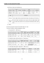
Item 

Description 

 BCC 

When the command is lowercase(r), only one lower byte of the value resulted by adding 1 Byte each 

to the ASCII values from NAK to ETX is converted into ASCII and added to BCC, and then sent. 


Содержание GLOFA G7M-DR20U

Страница 1: ...yReadthismanualcarefullybeforeinstalling wiring operating servicingorinspecting thisequipment y Keep this manual within easy reach for quick reference Programmable Logic Controller GLOFA GM7U...

Страница 2: ...ences are indicated by the following symbols This symbol indicates the possibility of death or serious injury This symbol indicates the possibility of injury or damage to property This symbol indicate...

Страница 3: ...off all output However one or more outputs could be turned on when there are problems that the PLC CPU cannot detect such as malfunction of output device relay transistor etc themselves or I O contro...

Страница 4: ...and damage to the product Completely turn off the power supply before loading or unloading the module Not doing so could result in electric shock or damage to the product Make sure all modules are loa...

Страница 5: ...ctly by checking the product s rated voltage and the terminal layout Incorrect wiring could result in fire damage or erroneous operation Tighten the terminal screws with the specified torque Loose ter...

Страница 6: ...it or solder the battery Mishandling of the battery could cause overheating or cracks resulting in injury and or fires Do not disassemble or modify the modules Doing so could cause erroneous operation...

Страница 7: ...fications 3 1 Chapter 4 Names of Parts 4 1 Main Units 4 1 4 1 1 60 Points Main Unit 4 2 4 1 2 40 Points Main Unit 4 5 4 1 3 30 Points Main Unit 4 8 4 1 4 20 Points Main Unit 4 10 4 2 Expansion Modules...

Страница 8: ...Failure 5 6 5 3 3 Scan Time 5 7 5 3 4 Scan Watchdog Timer 5 7 5 3 5 Timer Processing 5 8 5 3 6 Counter Processing 5 9 5 4 Program 5 12 5 4 1Program Configuration 5 12 5 4 2 Program Execution Procedur...

Страница 9: ...9 5 11 2 Structure 5 40 5 11 3 Usage 5 40 5 11 4 Read RTC Data 5 41 5 11 5 Write RTC Data 5 42 Chapter 6 Input and Output Specifications 6 1 Input Output Specifications 6 1 6 2 Digital Input Specifica...

Страница 10: ...3 1 Specification 7 77 7 3 2 Positioning Function 7 80 7 3 3 Positioning parameter and Operation Data 7 93 7 3 4 Instructions 7 100 7 3 5 Flag list and Error codes 7 110 7 3 6 Wiring with Servo and S...

Страница 11: ...on 8 83 8 4 1 Introduction 8 83 8 4 2 Parameter Setting 8 84 8 4 3 Function Block 8 85 8 4 4 Examples 8 87 8 5 Remote Connection and Communication I F module 8 89 8 5 1 Remote Connection 8 89 8 5 2 Co...

Страница 12: ...en the RUN LED turned off 11 4 11 2 4 Flowchart for when the I O devices does not operate normally 11 5 11 2 5 Flowchart for when unable to write a program to the CPU 11 7 11 3 Troubleshooting Questio...

Страница 13: ...ribes each component s usage Chapter 8 Communication Functions Describes built in communication functions Chapter 9 Installation and Wiring Describes installation wiring and handling instructions for...

Страница 14: ...ediate responses by using a built in 8 point interrupt input The input filter function helps to reduce the possibility of false input conditions from external noise such as signal chattering The filte...

Страница 15: ...PLC Operation mode is set to debug mode y Executed by one command y Executed by break point settings y Executed by the condition of the device y Executed by the specified scan time 11 Various program...

Страница 16: ...er supply Off occurrence will be informed to the user program and the PLC system restarts with the previous user defined data and user program after the power supply Off Hot Restart After the power we...

Страница 17: ...used to call S W packages for process supervision Task It means startup conditions for a program There are three types of periodic task internal contact task and external contact task which starts by...

Страница 18: ...pter 1 General 1 6 Terms Definition Remarks Source Output Current flows from the output terminal to the load and the PLC output turn on Fnet Fieldbus Network Cnet Computer Network Dnet DeviceNet Netwo...

Страница 19: ...U N DC G7M DT20 30 40 60U N G7M DRT20 30 40 60U N DC Main unit G7M DT20 30 40 60U P G7M DRT20 30 40 60U P DC Digital I O G7E DR10A G7E DR20A G7E TR10A G7E DC08A G7E RY08A G7E DR08A G7E RY16A A D D A G...

Страница 20: ...t and has also G7L CUEB for RS 232C G7L CUEC for RS 422 It is possible to construct communication systems on demand 1 1 1 Communications system 1 1 1 communication between PC and GM7U via RS 232C buil...

Страница 21: ...ple main units up to a maximum of 32 stations 1 Via RS 422 Cnet I F module 2 Via RS 485 Cnet I F module G7L CUEC RS 232C RS 422 Converter Max of 32 stations can be added G7L CUEC For details refer to...

Страница 22: ...unction Application program execution function Input The input signals obtained from the machine process to appropriate signal levels for processing Output The output signals obtained from the signal...

Страница 23: ...V DC DC10 8 26 4V G7M DRT40U N G7M DRT40U N DC 1 DC24V input 24 points 2 Relay output 12 points 3 NPN TR output 4 points 4 AC 85 264 V DC DC10 8 26 4V G7M DRT60U N G7M DRT60U N DC 1 DC24V input 36 poi...

Страница 24: ...0 1V D A 1 channel current output G7F AD2A A D 4 channels A D G7F AD2B A D 4 channels Slim type G7F DA2I D A 4 channels current output D A G7F DA2V D A 4 channels voltage output Slim type Analog timer...

Страница 25: ...Y Z axis IEC 61131 2 Square wave Impulse noise 1 500 V LSIS Standard Electronic discharge Voltage 4 kV Discharge by contact IEC 61131 2 IEC 1000 1 2 Radiated electromagnetic field noise 27 500 MHz 10...

Страница 26: ...dicates operating status of the main unit y On indicates local key switch or remote running mode y Off the following turns the LED off the supplied power to the main unit is abnormal the key switch is...

Страница 27: ...e operation y PAU REM the usage of each modules is as follow PAUSE temporarily stops the operation REMOTE remote driving Dip switch for Cnet I F See Chapter 5 Power Supply CPU RS 232C connector A conn...

Страница 28: ...Chapter 4 Names of Parts 4 3 2 G7M DRT60U N 3 G7M DT60U N 4 G7M DT60U P...

Страница 29: ...Chapter 4 Names of Parts 4 4 5 G7M DR60U DC 6 G7M DRT60U N DC 7 G7M DT60U N DC...

Страница 30: ...Chapter 4 Names of Parts 4 5 8 G7M DT60U P DC 4 1 2 40 point main unit 1 G7M DR40U 2 G7M DRT40U N...

Страница 31: ...Chapter 4 Names of Parts 4 6 3 G7M DT40U N 4 G7M DT40U P 5 G7M DR40U DC...

Страница 32: ...Chapter 4 Names of Parts 4 7 6 G7M DRT40U N DC 7 G7M DT40U N DC 8 G7M DT40U P DC...

Страница 33: ...Chapter 4 Names of Parts 4 8 4 1 3 30 point main unit 1 G7M DR30U 2 G7M DRT30U N 3 G7M DT30U N...

Страница 34: ...Chapter 4 Names of Parts 4 9 4 G7M DT30U P 5 G7M DR30U DC 6 G7M DRT30U N DC...

Страница 35: ...Chapter 4 Names of Parts 4 10 7 G7M DT30U N DC 8 G7M DT30U P DC 4 1 4 20 point main unit 1 G7M DR20U...

Страница 36: ...Chapter 4 Names of Parts 4 11 2 G7M DRT20U N 3 G7M DT20U N 4 G7M DT20U P...

Страница 37: ...Chapter 4 Names of Parts 4 12 5 G7M DR20U DC 6 G7M DRT20U N DC 7 G7M DT20U N DC...

Страница 38: ...Chapter 4 Names of Parts 4 13 8 G7M DT20U P DC...

Страница 39: ...0A 4 2 2 16 point I O expansion module 2 G7E RY16A No Names Input LED Output LED Input Contact Input Common Terminal Output Contact Output Common Expansion Cable Expansion Cable Connecting Terminal No...

Страница 40: ...put Contact Input Common Terminal Output Contact Output Common Expansion Cable Expansion Cable Connecting Terminal No Names Output LED Output Contact Output Common Terminal External Power Supply Termi...

Страница 41: ...es Output LED Output Contact Output Common Terminal Expansion Cable Expansion Cable Connecting Terminal No Names Input LED Output LED Input Contact Input Common Terminal Expansion Cable Expansion Cabl...

Страница 42: ...Analog Input Voltage current selecting jumper pin Analog Input Terminal External Power Supply Terminal DC24V Expansion Cable Expansion Cable Connecting Terminal 2 G7F ADHB Slim Type No Names RUN LED...

Страница 43: ...necting Terminal External Power Supply Terminal DC24V 2 G7F DA2V Slim Type No Names RUN LED D A Output Channel Expansion Cable Expansion Cable Connecting Terminal External Power Supply Terminal DC24V...

Страница 44: ...Power Supply Terminal DC24V Expansion Cable Expansion Cable Connecting Terminal 2 G7F AD2B No Names RUN LED Analog Input Terminal Analog Input Voltage current Selecting Jumper Pin External Power Suppl...

Страница 45: ...e No Names RUN LED Analog Timer Volume Control Resistor Expansion Cable Expansion Cable Connecting Terminal 4 3 5 RTD input module No Names RUN LED RTD Input Channel Expansion Cable Expansion Cable Co...

Страница 46: ...nal TM TC selecting dip switch No Names RS 422 485 connector Power supply Communication status LED Expansion cable Expansion cable connecting terminal No Names Station No selecting switch Fnet cable c...

Страница 47: ...No selecting switch NA DeviceNet cable connector Expansion cable Expansion cable connecting terminal Baud rate selecting switch Power supply Communication status LED No Names Station No selecting swi...

Страница 48: ...s or less Voltage DC 5V Output 1 Current 1 2 A 2 0 A Voltage DC24V Output 2 Current 0 2 A Power indicator PWR LED On when the power supply is normal 5 1 2 DC power supply Models Items G7M DR20U DC G7M...

Страница 49: ...nction block Function blocks for built in functions special communication modules Operator 0 1 0 9 s Processing speed Standard function function block Refer to the section Appendix 3 Program memory ca...

Страница 50: ...1 phase up counter 1 phase up down counter up down selection by B phase 2 phase up down counter up down pulse input 2 phase up down counter up down automatic selection by phase differen ce HSC Additi...

Страница 51: ...point Main Unit 60 point Main Unit Remarks Pulse catch Pulse width 10 2 points IX0 0 0 IX0 0 1 50 6points IX0 0 2 IX0 0 7 External interrupt 8 points 10 2 points IX0 0 0 IX0 0 1 50 6 points IX0 0 2 IX...

Страница 52: ...ng Stage for the start of a scan processing It is executed only one time when the power is applied or reset is executed It executes the following process I O reset Execution of self diagnosis Data cle...

Страница 53: ...t momentary power failure Momentary power failure occurs when the input voltage to the power supply falls below the rated voltage If there is momentary power failure under 10ms the CPU maintains opera...

Страница 54: ...cations service processing time 2 Scan time differs in accordance with the execution or non execution of interrupt programs and commun ication processing etc 2 Flag 1 Scan time is stored in the follow...

Страница 55: ...tting time process time setting time the Timer output contact turns on On Delay Timer Timing Diagram is shown as below 2 Off Delay Timer Process Time Change and Contact On Off y If input condition tur...

Страница 56: ...part counter increase decrease the present counting value by the detection of rising edge Off On of input signal Three types of counter are increment counter Decrement counter and Increment Decrement...

Страница 57: ...Decrement Counter It should have Increment input condition CU Decrement input condition CD load LD and setting value PV If reset signal R turns on counting value CV is set to 0 If load signal LD turns...

Страница 58: ...time and it will be counted when on time or off time of input condition is larger than each scan time Duty n is the percentage of On Off of the input signal T1 T2 100 2 1 1 T T T n T1 T2 100 2 1 2 T T...

Страница 59: ...terval setting In case of the processing need a shorter interval than that of average scan processing time In case of the processing needs a longer interval than that of average scan processing time I...

Страница 60: ...the I O refresh is still executed 3 Flag _INIT_RUN flag is on during executing the initialization program 2 Scan program 1 Function In order to process signal which repeats constantly the program exec...

Страница 61: ...programs are applicable Time driven task program The program is executed by the time internal set before Single internal task program The corresponding program will be executed at the rising edge and...

Страница 62: ...unction as the control panel executing programs Each task consists of more than one program blocks out of the 3 types of programs Those programs are called task program A program to which a task has n...

Страница 63: ...rity Level 0 to 7 Level 0 has highest priority Level 0 to 7 Level 0 has highest priority Level 0 to 7 Level 0 has highest priority 2 Task program processing method The following explains the common pr...

Страница 64: ...where program needs protection and EI function where program needs cancellation After the scan program ends of the running program automatically it becomes permissible Initialization program doesn t g...

Страница 65: ...has been occurred 3 Precautions for using an external contact task Input interrupt that is possible to set is up to IX0 0 0 IX0 0 7 While a task program which are designated by an input module having...

Страница 66: ...to ON and then from ON to OFF by scan program or time driven or external task program the task will not be executed as the execution condition can not be detected at the time that execution condition...

Страница 67: ...programs as shortly as possible 4 Protection of lower priority programs against higher priority program isn t needed during execution of those programs y If the priority of a task program or a scan p...

Страница 68: ...ed by E_INT1 of 7 ms but it is ignored because P3 is executing 8 10 P3 finishes its execution and the P0 stopped continues its execution 10 12 P0 is stopped and P1 is executed due to execution request...

Страница 69: ...t has occurred and continues its operation if an ordinary error such as battery error has occurred 2 System configuration error This error occurs when the PLC hardware configuration differs from the c...

Страница 70: ...ness 2 Operation processing contents I O refreshes and program operation are executed 1 Task programs are executed with the detection of their start up conditions 2 Normal or abnormal operation and mo...

Страница 71: ...ditions of the loaded module are checked 3 Communications service or other internal operations are processed 5 5 4 DEBUG mode In this mode errors of a program are searched and the operation sequence i...

Страница 72: ...y the specified scan number 5 5 5 Operation mode change 1 Operation mode change methods The following method is used to change the operation mode 1 Change by the mode setting switch of CPU module 2 Ch...

Страница 73: ...OP Remote RUN DEBUG X X Remote PAUSE Remote RUN Remote PAUSE Remote STOP Remote PAUSE Remote DEBUG X X DEBUG Remote STOP DEBUG Remote RUN X X PAU REM DEBUG Remote PAUSE X X 4 Remote operation mode cha...

Страница 74: ...been set to the warm restart mode cold restart will be executed at the first execution of a program after it has been changed 4 In case of selection Reset command in the GMWIN it restarts in accordan...

Страница 75: ...Initialized with 0 Previous value is retained Initialization Initialized with the user defined value Initialized with the user defined value Retain Initialization Initialized with the user defined va...

Страница 76: ...RUN STOP the CPU module under the condition that the mode selling switch of CPU module is in the remote position 2 This function is convenient when the CPU module is located on the place where it is d...

Страница 77: ...f output refresh the data of the junctions which have been set to force on off will be replaced with force setting data and the replaced data will be output However the force on off setting does not c...

Страница 78: ...ut complex programming and monitoring of the error location can be done without special tools GMWIN etc or source programs 1 External device fault detection and classification 1 The user program detec...

Страница 79: ...ill be shown as left after the scan has been finished _ANNUN_WR 1 _ANC_WAR 0 10 _ANC_WAR 1 1 _ANC_WAR 2 2 _ANC_WAR 3 3 _ANC_WAR 4 15 _ANC_WAR 5 40 _ANC_WAR 6 50 _ANC_WAR 7 60 After the next scan has b...

Страница 80: ...all program memory area 132 kbyte Parameter area Basic parameter area High speed link parameter area interrupt setting information area 7 8 kbyte Program area Scan program area Task program area User...

Страница 81: ...ze is QX0 0 0 QX1 7 63 In GM7U only QX0 0 0 QX0 3 63 can be used as a real input domain but the other unused domain can be used as convenience especially remote output data for communication can be sa...

Страница 82: ...a The rests are available to use as internal relay 2 The I O allocation method is as shown below Output QX0 0 0 QX0 0 23 QX0 1 0 QX0 1 3 QX0 3 0 QX0 3 3 5 9 Built in external Communication Setting Swi...

Страница 83: ...ystem downloading REMARK 1 The lower ROM mode switch is for the GM7U operating system downloading 2 Its ON status causes malfunction of the system so make sure to turn it off for the normal operation...

Страница 84: ...e external memory module 1 Turn the power of the base unit off 2 Install the memory module When only basic unit is used Connect to the expansion connector of the basic unit When expansion unit is used...

Страница 85: ...t When expansion unit is used connect to the expansion connector of the last connected expansion unit 3 Turn the power of the main unit On and set the PLC operation mode Run GM7U automatically reads t...

Страница 86: ...of year data Month 1 12 Date 1 31 Hour 0 23 24 hour Minute 0 59 Second 0 59 Day 0 6 Monday 0 Sunday 6 Century Indicate upper 2 digit of year data 2 Accuracy Max 2 2 sec 1 day At 25 C 3 RTC data back...

Страница 87: ...base unit Off 2 Install the G7E RTCA module When use the base unit only insert the RTC module into the expansion connector of the base When use the base unit and expansion unit insert the RTC module...

Страница 88: ...TC_ERR BOOL RTC Error Indicates 1 when and an RTC data error detected 0 _RTC_TIME n n 0 to 7 BCD Present time BCD data of present time of RTC _RTC _TIME 0 year _RTC _TIME 1 month _RTC _TIME 2 day _RTC...

Страница 89: ...There are two ways to write new RTC data to the CPU Select Menu Online PLC Information System Info If you want to setup or edit present time select Set Date Time Set Setup Date and Time in Date Time S...

Страница 90: ...1999 1 17 11 53 24 Sunday When the TIME_PRESET bit is switched on the new data in SET_TIME will be moved to _RTC_TIME SET_TIME variable setting z F B Error code The following table shows error codes...

Страница 91: ...use both of electric current sink and electric current source To keep use coil load as an output module maximum opening and shutting frequency is 1 second on and 1 second off The following diagram sho...

Страница 92: ...7 mA Operating voltage range DC20 4 28 8V ripple less than 5 Max simultaneous input points 100 simultaneously On On voltage On current DC19V or higher 5 7 mA or higher Off voltage Off current DC6V or...

Страница 93: ...ons 6 3 3 Input wiring Main unit s wiring method is as follows DC input specifications offered by GM7U is to be used for both electric current sink and electric current source 1 20 points main unit 2...

Страница 94: ...Chapter 6 Input and Output Specifications 6 4 3 40 points main unit 4 60 points main unit DC12 24V DC12 24V DC24V DC24V...

Страница 95: ...external device as shown External device Input Contact points NPN open collector output type NPN current output type PNP current output type Relay IN COM Sensor IN COM Power for sensor Output 0V IN CO...

Страница 96: ...pple less than 5 Max Simultaneous input points 100 simultaneously On On voltage On current DC19V or higher 5 7 mA or higher Off voltage Off current DC6V or lower 1 8 mA or lower Input impedance Approx...

Страница 97: ...oltage current DC24V 2A r load AC220V 2A COS 1 1 point 5A 1COM Min load Voltage current DC5V 1mA Max load voltage current AC250V DC110V Off leakage current 0 1mA AC220V 60Hz Max On off frequency 1 200...

Страница 98: ...Chapter 6 Input and Output Specifications 6 8 3 Output wiring 1 20 points main unit 2 30 points main unit DC5V DC24V AC110 220V DC5V DC24V AC110 220V...

Страница 99: ...Chapter 6 Input and Output Specifications 6 9 3 40 points main unit 4 60 points main unit DC5V DC24V AC110 220V DC24V DC5V DC24V AC110 220V DC24V DC24V DC24V...

Страница 100: ...ad voltage DC10 2 26 4V Max load current 0 5A point but QX0 0 0 QX0 0 1 0 1A Surge absorber Zener diode Off leakage current Less than 0 1mA Voltage drop when on Less than DC 0 3 V 0 1A Inrush current...

Страница 101: ...Chapter 6 Input and Output Specifications 6 11 2 Output wiring 1 20 points main unit 2 30 points main unit DC12 24V DC12 24V DC12 24V DC12 24V DC12 24V...

Страница 102: ...Chapter 6 Input and Output Specifications 6 12 3 40 points main unit 4 60 points main unit DC12 24V DC12 24V DC12 24V DC12 24V DC12 24V DC12 24V DC12 24V DC12 24V DC12 24V DC12 24V...

Страница 103: ...2 26 4V Max load current 0 5A point but QX0 0 0 QX0 0 1 0 1A Surge absorber Zener diode Off leakage current Less than 0 1mA Voltage drop when on Less than DC 0 3 V 0 1A Inrush current Less than 4A 10...

Страница 104: ...Chapter 6 Input and Output Specifications 6 14 2 Output wiring 1 20 points main unit 2 30 points main unit DC12 24V DC12 24V DC12 24V DC12 24V DC12 24V...

Страница 105: ...Chapter 6 Input and Output Specifications 6 15 3 40 points main unit 4 60 points main unit DC12 24V DC12 24V DC12 24V DC12 24V DC12 24V DC12 24V DC12 24V DC12 24V DC12 24V DC12 24V...

Страница 106: ...ff leakage current 0 1mA AC220V 60Hz Max on off frequency 1 200 times hr Surge absorber None Mechanical More than 20 000 000 Rated on off voltage current load 100 000 or more AC200V 1 5A AC240V 1A COS...

Страница 107: ...ent DC12V 24V Operating load voltage range DC10 2 26 4V Max load current 0 5A 1 point 4A 1COM Off leakage current 0 1mA or lower Max inrush current 4A 10ms or lower Max voltage drop when on DC 1 5V or...

Страница 108: ...n output When current value is equal to comparison value turns on the output contact points or executes interrupt program Additional function RPM function Calculate the RPM Rotates Per Minute of input...

Страница 109: ...ut terminal A Phase Input terminal IX0 0 3 Ch3 Input Ch2 B Phase Input Counter input terminal B Phase Input terminal IX0 0 4 Ch0 Preset 24V Ch0 Preset 24V Preset input terminal Preset input terminal I...

Страница 110: ...Preset input Ch2 Preset input Off 6V or lower On 20 4 28 8V I007 Ch3 Preset input Off 6V or lower Input COM0 Common 5 Wiring instructions A high speed pulse input is sensitive to the external noise an...

Страница 111: ...Various Functions 7 4 6 Wiring example 1 Voltage output pulse generator Pulse Generator CHSC A B COM 24V 24VG 2 Open collector output pulse generator Pulse Generator CHSC A B COM 24V 24VG Pulse Genera...

Страница 112: ...and it turns off when current value is less than set value If current value is greater than 2 147 483 647 carry flag F18 turns on and and it turns off when input condition turns off If HSC designated...

Страница 113: ...ettings refer to the section Chapter 8 High Speed Counter Parameter settings 8 High speed counter parameter settings 1 Format setting a Linear counter If HSC is designate as Linear counter it can coun...

Страница 114: ...eed counter is reaches 0 during down counting and current value is changed to set value 1 When set value is out of range 2 2 147 483 647 Ring counter setting error h 11 occurs and HSC operates as line...

Страница 115: ...alue decreases by 1 at the rising edge of A Phase pulse when B phase is High state c 2 phase CW CCW mode Current value increases by 1 at the rising edge of A Phase pulse when B phase is low state Curr...

Страница 116: ...Phase pulse when B phase is low At the rising edge of B Phase pulse when A phase is low At the falling edge of B Phase pulse when A phase is high 3 Preset setting a Internal Preset Set internal preset...

Страница 117: ...nt value can be cleared or changed 5 Comparison Output setting a Comparison set When current value of HSC is equal to SV1 corresponding output point turns on Only QX0 0 0 QX0 0 7are available for comp...

Страница 118: ...turns on Only QX0 0 0 QX0 0 7 are available If the set value of SV2 is less than SV1 SV2 setting error h 12 occurs and zone comparison set becomes disabled c Comparison Task When current value of HSC...

Страница 119: ...input the set value The RPM output displays the RPM value using the counter value s difference at every refresh cycle The RPM is expressed as cycle ms refresh rotate per Pulses 60 000 Value Last Valu...

Страница 120: ...counter 0 100 000 Counter mode 2 phase multiplication mode IX0 0 0 A phase pulse input IX0 0 1 B phase pulse input Preset change the current value to 0 when the value of MX100is 1 Preset type interna...

Страница 121: ...rts its operation If the current value is equal or more than 1 000 000 the output QX0 0 0 is On The current value is saved in CURRENT_VALUE Double Word QX0 0 3 turns On if the current value is equal o...

Страница 122: ...Chapter 7 Usage of Various Functions 7 15 REMARK The contact point which is designated as HSC input can t be used for pulse catch or external interrupt Duplicated designation may cause faults...

Страница 123: ...n But in this case through pulse catch function even narrow interval of pulse signal as 10 can be detected 2 Minimum input pulse width IX0 0 0 IX0 0 1 10 IX0 0 2 IX0 0 7 50 3 Operation input signal in...

Страница 124: ...noise occurs frequently or pulse width of input signal affects as a crucial factor In this case the user sets up the proper input on off delay time then the trouble by miss operation of input signal...

Страница 125: ...n Input Filter Time 3 For main unit the input filter time can be set as a unit of 7 points but for expansion unit it can be set at a time 4 Input filter time is set as default value of 10ms as one of...

Страница 126: ...integral I and derivative D The characteristics of the PID function of GM7U is as following the PID function is integrated into the CPU module Therefore all PID control action can be performed with in...

Страница 127: ...rge the PV reaches to the SV swiftly but it may causes a bad effect like oscillations e If the Kp is too small oscillation will not occur However the PV reaches to the SV slowly and an offset may appe...

Страница 128: ...3 The integral action with constant deviation The expression of I action is as following As shown in the expression Integral action can be made stronger or weaker by adjusting integration time Ti in...

Страница 129: ...iation by producing MV which is proportioned with the change velocity a velocity whose deviation changes at every constant interval in order to eliminate the deviation D action gives quick response to...

Страница 130: ...E Td Kp MV Derivative action is used only in PID action in which P and I actions combine with D action d PID action PID action controls the control object with the manipulation quantity produced by P...

Страница 131: ...operating state after the windup was occurred The Fig 7 8 shows the PV and MV of PI control system when the windup occurs As shown as the Fig 7 8 the actuator is saturated because of the large initia...

Страница 132: ...ontinuous formula of I control is as following Kp proportional gain constant Ti integral time E s deviation value By derivation about t we can obtain where e SV PV deviation value The digitized formul...

Страница 133: ...an error occurred or there is not execution request SV outputs current SV set value range 0 4000 MV outputs MV manipulation value range 0 4000 STAT outputs error code a Usage When the condition of the...

Страница 134: ...ion I The integral time constant obtained by auto tuning operation D the derivative time constant obtained by auto tuning operation a Usage When the condition of the execution is On PID auto tuning op...

Страница 135: ...e constant of system response for better performance Time constant is the time taken the system s step response reaches to the 63 of steady state 2 Operation mode MW4801 Select automatic or manual ope...

Страница 136: ...s by calculated manipulation value The figure below shows an example of PWM output Using PWM output PID control system can be constructed easily without D A conversion module and power regulator The o...

Страница 137: ...0 12 SV Target and PV Current SV setting value the designated value and PV process value present value of GM7U PID operation have the range 0 4000 The range is set with the consideration of the resolu...

Страница 138: ...es an absolute manipulate value MVn every sampling steps Generally The velocity form is suit for the system which s load change is slow like temperature control system and positioning form is useful f...

Страница 139: ...alent digital output of A D module current input range 4 20mA is 1500 if the A D module outputs 0 4mA with 200 C and 4000 20mA with 600 C Therefore the input of SV should be 1500 not 100 When using se...

Страница 140: ...is a output method which changes on off duty of output pulses by calculated manipulation value The figure below shows an example of PWM output Using PWM output PID control system can be constructed ea...

Страница 141: ...lue MV 0 4000 based on PID parameter settings P_GAIN I_TIME D_TIME etc and PV from RTD module Then the calculated MV is output to the channel 0 of D A module D A module will convert the MV to analog s...

Страница 142: ...elated items Derivative Integral Proportional select PWM when it is needed PWM contact When it is activated input proper values SV Ramp 500 when SV converted 500 0 5 sec 25 sec MV 4000 delta MV functi...

Страница 143: ...and the output value of control result registrate MW4100 output to channel 0 of D A conversion module When the input condition turns off it outputs 0 to the MW4100 channel 0 of D A conversion module W...

Страница 144: ...to tuning is completed and the calculate P I D constants are saved respectively in the designated value These values become the P I D control constant Program to execute the PID operation when the END...

Страница 145: ...W4104 Set Proportional Gain Derivational Time Integral Time BIAS 0 input proper value to use P control only Mode Command Set select the related items Derivative Integral Proportional select PWM when i...

Страница 146: ...0 channel 0 of D A conversion module When auto tuning is completed END output becomes 1 and the calculated P I D values are saved in MW4805 MW4807 MW4806 respectively When END output is On PID operati...

Страница 147: ...M only Do not set I D ID or PD H03 Scan time setting range error Set scan time to available setting range 1 100 H04 Manual operation range error Set manual operation value to available setting range H...

Страница 148: ...ption Countermeasure H12 Auto tuning direction parameter setting error Select forward or reverse operation H13 LOOP duplication error Do not execute the auto tuning using the parameters used in other...

Страница 149: ...D A value CH0 D A value CH0 D A value CH2 A D value CH2 D A value CH2 A T value MW4166 CH2 Temperature value MW4107 Analog module 2 CH1 D A value CH3 A D value CH3 D A value CH3 A T value MW4167 CH3 T...

Страница 150: ...Voltage DC 12V Analog Input Absolute max input Current DC 24 mA Voltage DC 0 10V External resistance 2 1 Fixed as voltage output Output range Current DC 0 20 External resistance 510 DC 4 20 External...

Страница 151: ...rrent CH0 CH1 Right is CH 1selecting Connect upper part Connect lower part Left is CH 0 selecting with jumper pin with jumper pin Analog output terminal Voltage output Current output Only one type of...

Страница 152: ...0 Ch1 Right current input Left voltage input Analog output terminal Voltage output Current output External power supply terminal Supplies DC 24V Extension cable A cable to connect analog combination m...

Страница 153: ...og input terminal Voltage input Analog output terminal Voltage output External power supply terminal Supplies DC 24V DC24V Extension cable A cable to connect analog combination module Expansion cable...

Страница 154: ...utput range is not matched In case that input output is current this function is useful that external equapment range is not matched each other GM7U series converts range automatically as following 0...

Страница 155: ...ixture module of AC and analog I O is not affected by induction noise or occurs from the AC through using another cable Wire is adopted with consideration about peripheral temperature and electric cur...

Страница 156: ...cteristics For G7F ADHA ADHB a Voltage input In voltage input digital amount 0 is output by 0V input and 4 000 is output by 10V input Therefore input 2 5mV equals to digital amount 1 but value less th...

Страница 157: ...HA ADHB a Voltage output Input of digital amount 0 outputs analog amount 0V 4000 does 10V Digital input 1 equals to 2 5mV of analog amount 2004 2002 2001 2000 2003 10 000 10 005 Input Current Digital...

Страница 158: ...igital value of channel 0 is less than 2000 QX0 0 0 is On when digital value of channel 0 is more than 3000 P091 is on QX0 0 1 is On When digital value of channel 0 is more or same than 2000 or lesser...

Страница 159: ...Chapter 7 Usage of Various Functions 7 52 c Program...

Страница 160: ...voltage of 5 steps a Program explanation When QX0 0 0 turns On 2000 5V is output When QX0 0 1 turns On 2400 6V is output When QX0 0 2 turns On 2800 7V is output When QX0 0 3 turns On 3200 8V is output...

Страница 161: ...and I terminal Input range is classified by GMWIN parameter settings Digital output 12 bits 0 4000 DC 0 10V 2 5 1 4000 DC 0 20 5 1 4000 Maximum resolution DC 4 20 6 25 1 3200 Overall accuracy 0 5 Full...

Страница 162: ...ort the V and I terminal Jumper pin for analog input Voltage input Current input Connect left parts Connect right parts by jumper pins by jumper pins External power supply terminal Supplies DC 24V Ext...

Страница 163: ...terminal Jumper pin for analog input Input Select Ch0 Ch1 Ch2 Ch3 Right for current Left for voltage External power supply terminal Supplies DC 24V Extension cable A cable to connect analog input modu...

Страница 164: ...is adopted with consideration about peripheral temperature and electric current allowance For wire thicker than AWG22 0 3 one is recommended If wire is put near to high temp radiated device or contact...

Страница 165: ...becomes output 0 10mA does 2000 and 20mA does 4000 therefore input 5 equals to digital amount 1 but value less tan 5 can t be converted So abandon it Digital Output Value Digital Output Value 2004 200...

Страница 166: ...0 is On When digital value of channel 1 is the same or more than 2000 and the same or less than 3000 QX0 0 1 is On When digital value of channel 2 is the same or more than 2000 and the same or less t...

Страница 167: ...Chapter 7 Usage of Various Functions 7 60 b System configuration Main unit A D conversion module Expansion module c Program...

Страница 168: ...t 12 bits 0 4000 No of channel 4 channels 1 module Max absolute output DC 24 DC 12V DC 0 20 5 1 4000 Maximum resolution DC 4 20 6 25 1 3200 2 5 1 4000 Accuracy 0 5 Full Scale Max conversion speed 500u...

Страница 169: ...7F DA2V Analog output terminal Analog current voltage output terminal External power supply terminal Supplies DC 24V Extension cable Cable to connect analog output module Extension cable connector A c...

Страница 170: ...Chapter 7 Usage of Various Functions 7 63 3 Parameter setting Data clear when changed to ST 1 Set PLC ST mode for each channel 2 Data clear when changed to PLC STOP mode output value 0...

Страница 171: ...signal of the mixture module of AC and analog I O is not affected by induction noise or occurs from the AC through using another cable Wire is adopted with consideration about peripheral temperature...

Страница 172: ...1 I I GND Less than 510 1 I I GND Less than 510 CH0 CH3 15V z The common grounding with other devices is not permitted when D A conversion module is used as current output type REMARK CH 3 Device CH 0...

Страница 173: ...equals to 2 5mV of analog amount D A conversion characteristics Current output D A conversion characteristics Current output Analog output voltage 10V 5V 0V 0 2000 4000 Digital input value Analog out...

Страница 174: ...0 10V a Program explanation 0 channel of the expansion module no 1 When QX0 0 0 is On 2000 10 5V is output When QX0 0 1 is On 2400 12 6V is output When QX0 0 2 is On 2800 14 7V is output When QX0 0 3...

Страница 175: ...y about max value Internal current consumption 50 Weight 200g Analog module 1 Analog module 2 Analog module 3 A T conversion value data register MW4160 MW4163 MW4164 MW4167 MW4168 MW4171 2 Names of pa...

Страница 176: ...1 Program Program which controls on delay time of output contact point within 0 to 200 ms by analog timer module Timer T000 starts to count and turns on QX0 0 0 when it reaches the value of MD100 2 S...

Страница 177: ...perature input point 4 channel 1 module No of module installation Max 3 modules Insulation Photo coupler insulation between the input terminal and the PLC power supply non insulation between channels...

Страница 178: ...value Digital conversion value Remark 0 MW4120 MW4100 1 MW4121 MW4101 2 MW4122 MW4102 3 MW4123 MW4103 Analog module 1 0 MW4124 MW4104 1 MW4125 MW4105 2 MW4126 MW4106 3 MW4127 MW4107 Analog module 2 0...

Страница 179: ...n 0 Normal run status 16 10h A disconnection detected Fix the A disconnection between RTD input module and RTD 17 11h B disconnection detected Fix the A disconnection between RTD input module and RTD...

Страница 180: ...s inputted by the internal burn out detection circuit and burn out detection error code is generated The RTD input module can detect disconnection for each channel But burn out detection is possible o...

Страница 181: ...xternal 24V DC power supply In case of wiring with high voltage line or generation line it makes induction failure so then it may cause of miss operation and out of order 2 Wiring example Number of me...

Страница 182: ...gram for output of detected temperature value as a BCD value a Program explanation The present A D conversion value of the detected temperature value which is detected from the temperature measuring r...

Страница 183: ...Chapter 7 Usage of Various Functions 7 76 c Program...

Страница 184: ...range 2 147 483 648 2 147 483 647 Speed Max 100kpps Speed setting range 5 100 000pps unit of pulse Acceleration Deceleration method Operation pattern Trapezoidal method Acceleration time 0 10 000 uni...

Страница 185: ...utput Ch0 Direction output terminal QX0 0 3 Direction output Ch1 Direction output terminal COM0 COM1 COM2 Common Pulse output common terminal P 24V External 24V supply terminal Positioning function is...

Страница 186: ...lse output Ch0 Internal circuit R R COM0 Output common 0 QX0 0 2 Direction output Ch0 QX0 0 3 Direction output Ch1 COM2 Output common 2 R R R R R R Motor driver For Ch0 24V DC 24V R R Motor driver For...

Страница 187: ...etting Items of positioning data Step No Coordinate Operation method Goal address Speed pps Dwell time Setting 1 Absolute Single 8 000 5 000 100 B Control by Incremental method Relative coordinate Pos...

Страница 188: ...tive number 0 included Reverse direction when position address is negative number Forward direction Reverse direction Set second operand of POSVEL instruction to 0 Set second operand of POSVEL instruc...

Страница 189: ...p without additional start command Continuous When one operation step has over executes next operation step without Deceleration Operation methods are as follows Operation method Remark Single When on...

Страница 190: ...peration action is trapezoid type operation that has acceleration constant deceleration section according to the setting speed and position data Example End operation Parameter setting No of program s...

Страница 191: ...e done B Keep operation mode is available to execute several operation step in order C Operation direction shall be determined by position address Example Keep operation Parameter setting No of progra...

Страница 192: ...continuous operation command is available C With Next Move continuous operation command the operation in the acceleration constant speed deceleration section of Continuous operation is available D Op...

Страница 193: ...eat step no change command after positioning completion of Repeat operation mode C Operation direction shall be determined by position address Example Repeat pattern Parameter setting No of program st...

Страница 194: ...n stop POSCTR If encounters deceleration stop command during operation it stop operation after deceleration In case of deceleration stop by deceleration stop command in acceleration or constant speed...

Страница 195: ...e origin return from parameter are as follows A Origin return speed high speed low speed B Origin return dwell time 2 Origin Detection when Approximate origin turns off This is the method using the ap...

Страница 196: ...stops 4 Origin Detection by approximate origin This is the method using the approximate origin signal only Speed Time Origin return low speed Origin signal Approximate origin signal Transfer amount af...

Страница 197: ...eration deceleration B If speed operand of POSJOG command as device not constant JOG speed can be changed from low speed to high speed or high speed to low speed during operation C If Jog speed is set...

Страница 198: ...input stroke Low limit has not detected On External input stroke Low limit has detected IX0 0 1 Ch0 Off External input stroke High limit has not detected On External input stroke High limit has detec...

Страница 199: ...e output 2 With M Code output Go on operation End operation Indirect operation Completion flag Current step Step M Step N Go on operation End operation Indirect start Completion flag Current step Step...

Страница 200: ...failure error occurs during operation the operation will stop If external high low limit external emergency stop during the positioning operation are detected during the positioning operation it stops...

Страница 201: ...celeration time the time required to reach from the speed limit set by parameter to the speed 0 stop state In case of using BIAS it is the time required to reach from the speed limit set by parameter...

Страница 202: ...on in command to smooth the rotation of motor and reduce the positioning time The speed to be set at this time is called Bias Speed The setting range is 5 10 000 unit 1pps at each axis Bias speed shal...

Страница 203: ...ange 5 100 000 unit 1pps Origin return Low speed The speed that acts to the constant speed section via deceleration section by origin return command Origin return low speed setting range 5 100 000 uni...

Страница 204: ...tion and deceleration section is controlled by JOG acceleration deceleration time JOG high speed setting range 5 100 000 unit 1pps notices when setting the high speed Bias speed Jog high speed Speed l...

Страница 205: ...ition Goal position reverse direction positioning B Relative Coordinate Control by Incremental method This carries out the positioning control as much as goal transfer amount from the current position...

Страница 206: ...ed can be assigned for each operation step No Setting range of operation speed 5 100 000 Setting unit 1pps The change of speed value is available when assigned by D area 7 Dwell Time This is the waiti...

Страница 207: ...operation is edge triggered 2 Example program When input condition MX000 turns on Ch 0 starts positioning from Step no 1 Function block Description Input REQ Executes POSIST function block CH Sets the...

Страница 208: ...nd turns Off if an error occurs or there is no execution command STAT Displays error status 1 Functions When input condition turns on corresponding Ch Starts JOG operation If input condition turns off...

Страница 209: ...block is executed without error and turns Off if an error occurs or there is no execution command STAT Displays error status 1 Functions Operates designated control operation at the rising edge of inp...

Страница 210: ...value 2 147 483 648 2 147 483 647 Output DONE Turns On after the function block is executed without error and turns Off if an error occurs or there is no execution command STAT Displays error status...

Страница 211: ...nction block is executed without error and turns Off if an error occurs or there is no execution command STAT Displays error status 1 Functions When input condition turns on the period pulse is output...

Страница 212: ...k is executed without error and turns Off if an error occurs or there is no execution command STAT Displays error status 1 Functions When input condition turns on rising edge corresponding Ch starts s...

Страница 213: ...without error and turns Off if an error occurs or there is no execution command STAT Displays error status 1 Functions When input condition turns on rising edge Operation speed of corresponding Ch cha...

Страница 214: ...0 Output DONE Turns On after the function block is executed without error and turns Off if an error occurs or there is no execution command STAT Displays error status 1 Functions When input condition...

Страница 215: ...error and turns Off if an error occurs or there is no execution command STAT Displays error status 1 Functions When input condition turns on corresponding origin return operation starts Rising edge t...

Страница 216: ...100 Output DONE Turns On after the function block is executed without error and turns Off if an error occurs or there is no execution command STAT Displays error status 1 Functions When input conditio...

Страница 217: ...icates stroke low limit detection of Ch0 Bit 4 _P0_H_LIMIT BOOL High limit detection Indicates stroke high limit detection of Ch0 Bit 5 _P0_E_STOP BOOL Emergency stop status Indicates emergency stop s...

Страница 218: ...t detection of Ch1 Bit 4 _P1_H_LIMIT BOOL High limit detection Indicates stroke high limit detection of Ch1 Bit 5 _P1_E_STOP BOOL Emergency stop status Indicates emergency stop status Ch1 0 enable 1 D...

Страница 219: ...s out of range Stop Set Dwell time of pulse out parameter within 0 10000 H30 POSIST command can t be executed during operation Operating Check if positioning operation is executing when POSIST signal...

Страница 220: ...ccur H46 POSORG command can t be executed when output is prohibited Stop Check if output is prohibited when POSORG signal occur Output can be enabled by POSCTR command H47 POSCTR setting error Check c...

Страница 221: ...U N 3 4 DOG Signal name CW CW CCW CCW TIMING COM DC5V Max 2m Stepping Motor Driver Pulse DC24V P40 P41 Ch0 Ch1 Direction P42 P43 Common COM0 COM1 Common COM2 COM2 Input 0V 0V 0V Origin P04 P06 P05 P0...

Страница 222: ...origin approximate origin point and upper lower limit signal are fixed but if they re not used you able to use them general input point You can use emergency stop with the command POSCTR 4 Positionin...

Страница 223: ...18 ZSP 19 TLC 6 P15R 11 TLA 12 LG 1 SD Plate CN1E TE11 MR J2S A U V W PE PE HC MF HA FF Series motor U V W E EMG 24VDC CN2 B1 B2 SM 2 1 12 TxD RxD LG 11 5 15 LG LG LG 4 3 14 13 Plate GND RS CS DR ER C...

Страница 224: ...0VAC NF RD SD GND GND RS CS DR ER L1 L2 L3 L11 L21 CTE2 D P CN1A PG 13 PP 3 NG 12 OPC 11 COM 9 EMG 15 SON 5 RES 14 PC 8 TL 9 LSP 16 LSN 17 SG 10 SG 20 VDD 3 COM 13 ALM 18 ZSP 19 TLC 6 P15R 11 TLA 12 L...

Страница 225: ...COM2 COM2 Input 24V P P Origin P04 P06 High Limit Low Limit Emergency Stop Common DOG 2 P05 P07 P01 P03 P00 P02 Input point COM0 Input 1 3 4 NPN Type PPFIN PFIN PPRIN PRIN PZO PZO RDY INPOS 11 10 9 1...

Страница 226: ...origin approximate origin point and upper lower limit signal are fixed but if they re not used you able to use them general input point You can use emergency stop with the command POSCTR 3 Using DC 2...

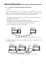
Страница 227: ...iting of device Reading CPU status Monitor devices registration Executing monitoring 1 1 connection link between GM7Us system configuration GM7U main unit RS 232C GM7U built in communication function...

Страница 228: ...ting system configuration link between GM7Us 1 1 1 connection with general PC a Communication program made by C or BASIC computer language on the user s computer or utility program like FAM or CIMON c...

Страница 229: ...tions 8 3 2 1 1 connection with a monitoring device like XGT Panel a Wiring The wiring diagram using RS 232C I F is as follow The wiring diagram using RS 485 I F is as follow XGT Panel LSIS GM7U main...

Страница 230: ...8 Communication Functions 8 4 3 1 1 connection with LSIS The wiring diagram using RS 232C I F is as follow The wiring diagram using RS 485 I F is as follow GM7U main unit RS 232C I F GM7U main unit RS...

Страница 231: ...eader Tale 2 ACK Response frame GM7U main unit external communication device when receiving data normally Max 256 Byte ACK 161 160 Structured data area or null code ETX BCC Command type Command Statio...

Страница 232: ...equal to hexadecimal value if there s no clear statement The terms in hexadecimal are as follows Station No When the main command is R r or W w and the command type is numerical means a data type All...

Страница 233: ...device Continuous w W H77 H57 SB 5342 Writes data to Byte and Word type in block unit Continuous reading Bit is unavailable CPU Status reading r R H73 H53 ST 5354 Reads flag list like PLC operation s...

Страница 234: ...direct variables Available types of device M internal memory Q output I input When direct variable is used attach 25H in front of the characters Data type Characters Examples Bit X 58H MX0 QX0 0 0 IX...

Страница 235: ...en H01 ASCII value 3031 H10 ASCII value 3030 Device length This indicates the number of device name s characters which is allowable up to 16 characters This value is one of ASCII converted from HEX ty...

Страница 236: ...In data area there are the values of HEX data converted to ASCII code saved Frame check BCC When the command is lowercase r only one lower byte of the value resulted by adding 1 Byte each to the ASCI...

Страница 237: ...W0 0 1 Computer request format PC GM7U main unit Format name Header Station No Command Command type Number of blocks Variable length Format name Device length Format name Tail Frame check Frame ENQ H0...

Страница 238: ...racters This value is one of ASCII converted from HEX type If the device name is MW0 it has 4 characters to be H04 If the device name is QW0 0 0 it has 8 characters to be H08 Device name Address to be...

Страница 239: ...me check BCC When the command is lowercase r only one lower byte of the value resulted by adding 1 Byte each to the ASCII values from ACK to ETX is converted into ASCII and added to BCC and then sent...

Страница 240: ...MD0 of station no 10 is read In this case H12345678 is in MD0 and H9ABCDEF0 is in MD1 PC request format PC GM7U main unit Format name Header Station No Command Command type Data length Variable name...

Страница 241: ...If the device name is QW0 0 0 it has 8 characters to be H08 Device name Address to be actually read is entered This must be ASCII value within 16 characters and in this name digits upper lower case o...

Страница 242: ...the ASCII values from NAK to ETX is converted into ASCII and added to BCC and then sent Error code Hex and 2 bytes ASCII code 4 bytes indicate error type For the details see 8 1 8 Error codes 5 Examp...

Страница 243: ...ne of ASCII converted from HEX type If the device name is MW0 it has 4 characters to be H04 If the device name is QW0 0 0 it has 8 characters to be H08 Device name Address to be actually read is enter...

Страница 244: ...e This example assumes that HAA15056 is written in QD0 0 0 at station no 1 PC request format PC GM7U main unit Format name Header Station No Command Command type Variable length Variable name No of da...

Страница 245: ...ered 0 to 9 H00 H09 If a registered no is registered again only the one currently being executed is registered Register format This is used to before EOT in command individual reading of direct variab...

Страница 246: ...sumes that the direct variable MW0 of station no 1 is registered for monitoring PC request format PC GM7U main unit Registration format Format name Header Station No Command Registra tion No Command N...

Страница 247: ...the command is lower case y only one lower byte of the value resulted by adding 1 byte each to the ASCII values from ENQ to EOT is converted into ASCII and then added to BCC 3 GM7U main unit response...

Страница 248: ...1 at station no 1 is read and the BCC value is checked It is also assumed that the device MW0 is registered and the number of blocks is 1 PC request format PC GM7U main unit Format name Header Station...

Страница 249: ...ription BCC When the command is lowercase r only one lower byte of the value resulted by adding 1 Byte each to ASCII values from ACK to ETX is converted into ASCII and then added to BCC and sent PLC s...

Страница 250: ...ror codes 5 Example This example supposes that the status of GM7U Main unit of station no 1 is read Computer request Format PC GM7U Main Unit Format name Header Station No Command Command type Tail Fr...

Страница 251: ...ock Up to 32 stations can be connected When using built in RS 485 Ch 1 G7L CUEC It can reestablish flag in relation with error codes and slave PLC operating mode according to parameter setting It can...

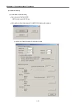
Страница 252: ...etting 1 Communication Parameter Setting Open a new project file from GMWIN GM7U must be selected for PLC type After selecting communication parameter from GMWIN the following window pops up a When us...

Страница 253: ...Chapter 8 Communication Functions 8 27 b When uses Ch 1 Built in RS 485...

Страница 254: ...by Cnet I F module G7L CUEC Notes RS232C dedicated modem and RS232C dial up modem communication can be processed only by Cnet I F module G7L CUEC support RS 232C not Cnet I F module G7L CUEC supportin...

Страница 255: ...it s not possible to set a register number b Sending and receiving data size can be set up to 60 Words There is no period for sending and receiving c Set device area Sending reading device area I Q M...

Страница 256: ...is in the slave station for the data to be read To Area It is in the slave station to write the data It is in the master station to temporarily save the data to be read When selecting MW0 click MW an...

Страница 257: ...errun error for the responding time of sending receiving Error code 2 NAK time error 3 Slave PLC mode and error description of each station total 32 stations Flag name _SRS_STATE n n 0 31 Data type ar...

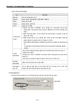
Страница 258: ...tact of the expansion digital I O module G7E DR10A 1 MASTER station s parameter settings and program Station No Select 1 0 31 available Baud rate Select 19200 1200 2400 4800 9600 19200 38400 57600 Par...

Страница 259: ...ion Functions 8 33 After setting the following window will be displayed Select 0 to set the master station s sending parameter After parameter settings click OK Station No Size Mode From area To area...

Страница 260: ...Chapter 8 Communication Functions 8 34 When the item 0 is registered the following window is show up Slave station s area Station No 31...

Страница 261: ...er as below After parameter settings click OK Station No Size Mode From area To area 31 1 Receive QW0 O O Q0 1 0 Check the item 0 and 1 are registered in the Entry list and Close the window Slave stat...

Страница 262: ...ing the parameter settings 2 Slave station s parameter settings Station No Select 31 0 31 available Baud rate Select 19200 1200 2400 4800 9600 19200 38400 57600 Parity bit None None Even Odd available...

Страница 263: ...error When omit When omit at QX command Check the data type and execute again H2232 Exceeded area error When the assigned area is exceed Ex 1 QX0 0 64 exceed assigned area MB0 0 8 exceed assigned are...

Страница 264: ...a 1 N inverter as slave system using LS BUS ASCII protocol This system can be built easily with communication parameter settings in GMWIN Up to 31 inverters can be used for each channel channel 0 cha...

Страница 265: ...r Communication Parameter in GMWIN and select channel 0 or channel 1 Selecting Channel 0 Selecting Channel 1 After selecting the figure below will be displayed Left for Channel 0 right for Channel 1 S...

Страница 266: ...er station s number Stations No 0 to 31 is available Select Send to write data to an inverter Select Receive to read data from inverter Size is the data size to send and receive and 1 to 8 words are a...

Страница 267: ...through the defined protocol For this protocol frame must be defined in GMWIN And exact knowledge about the contents of the protocol defined by the user is vital in making the communication possible G...

Страница 268: ...g through the telephone line by dial up modem and Cnet I F module G7L CUEB Remark Using Cnet I F module G7L CUEB supporting RS232C RS232C dedicated or dial up modem communication can be done but not t...

Страница 269: ...ilable Control Code NUL H00 SOH H01 STX H02 ETX H03 EOT H04 ENQ H05 ACK H06 BEL H07 BS H08 HT H09 LF H0A VT H0B FF H0C CR H0D SO H0E S1 H0F DLE H10 DC1 H11 DC2 H12 DC3 H13 DC4 H14 NAK H15 SYN H16 ETB...

Страница 270: ...he data needed for interactive communication ARRAY type must be always set by byte Ex 1 MB0 QB0 0 0 Ex 2 MX0 MW0 MD0 QX0 0 0 QW0 0 0 This field is to declare commands and fixed data that will be used...

Страница 271: ...as headers are 1 alphabet letter 1 numeric number or control characters as below Available Control Code NUL H00 SOH H01 STX H02 ETX H03 EOT H04 ENQ H05 ACK H06 BEL H07 BS H08 HT H09 LF H0A VT H0B FF...

Страница 272: ...CC method is OR Exclusive OR XOR 2 BCC method is the same with XOR 1 but it s used when the user masks any value to the last BCC value MUL 1 BCC method is MULTIPLY that is multiplication Check Rule MU...

Страница 273: ...6 If the received frame is matched with the declared frame in frame list number 3 _RCV 3 starts blinking 0 1 0 Channel 0 _RCV n n frame list number Channel 1 _RCV1_422 n n frame list number When frame...

Страница 274: ...value of sum check ASCII Type Hex Type ASCII Input 05 31 32 33 34 04 05 05 31 32 33 34 04 30 35 05 31 32 33 34 04 05 Hex Input 05 12 34 04 27 05 12 34 04 32 37 05 12 34 04 27 MUL 1 The last transmitt...

Страница 275: ...is set to 1 and keeps till the next request for function block ERR When an error occurs this is set to 1 and keeps till the next request for function block STATUS When an error occurs output error cod...

Страница 276: ...ion This example assumes that there s a communication between LSIS products by the user defined protocol The system configuration is as follows and the cable is the same with the one of 1 1 dedicated...

Страница 277: ...method and channel setting select Master at User defined in Protocol and mode Set the parameters according to the following table Communication Method Protocol and Mode Station no Baud rate Data bit...

Страница 278: ...pter 8 Communication Functions 8 52 Select Frame 0 to define the Tx frame Item Setting value Header ENQ Tx Rx Receive Segment 1 Type CONST Field SND_FRAME Segment 2 Type ARRAY Field MB000 Tailer EOT B...

Страница 279: ...3 BCC is set in tail after setting Click BCC Setting to activate the BCC setting window Set as follows and click OK to close Item Setting value Type ASCII Check rule Default Click OK and then the foll...

Страница 280: ...List 1 and set as below Item Setting value Header STX Tx Rx Receive Segment 1 Type CONST Field RCV_FRAME ASCII Input Segment 2 Type ARRAY Field MB10 Size 4 Byte Tailer ETX After the frame setting clic...

Страница 281: ...OK to complete setting 5 Setup a program like the following figure and download it to the slave station of GM7U For detailed program setting and downloading information refer to the GMWIN manual Inse...

Страница 282: ...from MBO of the master station Frame 1 is saved in MB10 refer to frame setting of Frame 1 and the saved MB10 value is reversed and outputted at QB0 0 0 The output value of QB0 0 0 is saved again in MB...

Страница 283: ...file and make a new program for the slave station Click the list after set the communication method and communication channel Set the parameters according to the following table and click OK Communic...

Страница 284: ...ing value Header ENQ Tx Rx Receive Segment 1 Type CONST Field RCV_FRAME ASCII Input Segment 2 Type ARRAY Field MB0 Size 4 Byte Tailer EOT BCC 4 BCC is set in tail after setting click BCC Setting to ac...

Страница 285: ...Chapter 8 Communication Functions 8 59 Click OK to see the Frame List 5 Click Frame List 1 to activate the Frame 1 window and set as follows...

Страница 286: ...t Segment 2 Type ARRAY Field MB10 Size 4 Byte Tailer ETX Set BCC following the master station 6 Click OK after frame setting and then the frame is registered as below 7 Set up a program like the follo...

Страница 287: ...outputs the value to QB0 0 0 The ouputted value of QB0 0 0 is saved again in MB10 If the execution is completed without errors Frame 1 is sent from function block Frame 1 sends 4 byte data saved in MB...

Страница 288: ...ructure ASCII data Item Header Address Function code Data LRC Tail CR LF Size 1 byte 2 bytes 2 bytes n bytes 2 bytes 2 bytes 2 RTU mode 1 It communicates using hex data 2 There s no header and tail It...

Страница 289: ...e part here because only function codes are different Request 0000 0011 16 03 Confirm 0000 0011 16 03 Confirm 1000 0011 16 83 5 Data area 1 It sends data using ASCII data ASCII mode or hex RTU mode 2...

Страница 290: ...any division of output contact points 0XXXX input contact points 1XXXX output registers 4XXXX input registers 3XXXX This means that the output contact point 1 0001 of Modicon products is marked as com...

Страница 291: ...ction 8 65 10 Wiring GM7U main unit Quantum 9PIN Pin no Connecting no and direction Pin no Signal 1 1 CD 2 2 RXD 3 3 TXD 4 4 DTR 5 5 SG 6 6 DSR 7 7 RTS 8 8 CTS 9 9 For channel 2 use RS 485 connector 1...

Страница 292: ...communication parameter 1 Open a new project file at GMWIN z GM7U should be selected in PLC types z Open a new project file for each of the master and the slave 2 Select a communication parameter at G...

Страница 293: ...odem with Cnet I F module G7L CUEB z RS232C Dial Up Modem It s to be selected for the general communication connecting through the telephone line by dial up modem and Cnet I F module G7L CUEB Footnote...

Страница 294: ...its in Modbus protocol communication Function code 01 reads Coil Status data and function 02 reads Input Status data 2 Error It outputs error codes to output STATUS Refer to Error codes for the detail...

Страница 295: ...le Value to save Variable Value to save Variable Value to save Variable Value to save RD_DB0 0 1 RD_DB0 10 0 RD_DB0 20 1 RD_DB0 30 0 RD_DB0 1 0 RD_DB0 11 1 RD_DB0 21 1 RD_DB0 31 0 RD_DB0 2 1 RD_DB0 12...

Страница 296: ...n block input Input value REQ Enter the input condition to operate CH 16 1 or 1 Set channel 1 SLV_STNO 16 11 or 17 Slave station FUNC 16 02 or 2 Enter 2 when the Coil status is being read SLV_ADDR 16...

Страница 297: ...declared as same as or bigger than data size NDR If it ends without error output 1 and keep the value till the call for the next function block ERR If an error occurs output 1 and keep the value till...

Страница 298: ...ata of the data address doesn t need to be input Because it s automatically processed by the input value of the input FUNC of the function block NUM 16 03 or 3 The total data size to read Example is t...

Страница 299: ...ead SLV_ADDR 16 08 or 8 The start address to read from slave station Read the no 8 to read starting from the output register 30009 in accordance with the previous no 8 Modbus addressing rules And the...

Страница 300: ...Input NUMH is set as 255 or HFF it writes 1 on the output coil If the Input NUMH is set as 0 or 16 00 it writes 0 on the output coil And function 06 writes 1 word data on the Output Holding Register 2...

Страница 301: ...6 as writes 1 word on the Holding Register ADDR 16 0001 or 1 Set the starting address to write on the slave station Write on no 1 to write on starting from the Holding Register 40002 in accordance wi...

Страница 302: ...e Holding Registers 2 Error It outputs error codes to output STATUS Refer to Error codes for the detailed 3 Example of the program z It s supposed that GM7U main unit is the master and it writes bits...

Страница 303: ...Input 16 0A z Result From the 2 bytes 16 bits sent only the low 10 bits are valid as set for its size Coil 00029 00028 00027 00026 00025 00024 00023 00022 00021 00020 Status 0 1 1 1 0 0 1 1 0 1 z It s...

Страница 304: ...e in function block 02 Illegal Address Error of exceeding the area limit of reading writing on the slave station 03 Illegal Data Value Error when the data value to be read from or write on the slave s...

Страница 305: ...MX0 through MOD0102 function code 01 and again saves 0 at MX0 MX9 using function block MOD1516 function code 15 then reads MW0 through Mod0304 The cable used in this example is same with that used fo...

Страница 306: ...ed program setting and downloading refer to GMWIN manual The program of the slave is to output the data at M area to the output contact coil 2 Setting s and the program for the master station 1 Create...

Страница 307: ...parameters as the following table Communication Method Protocol and Mode Station No Baud Rate Data Bit Parity Bit Stop Bit Communication Channel Modbus Transmission Mode 1 38400 7 Even 1 RS 232C Null...

Страница 308: ...is on for 1 scan z Previous function blocks NDR output is the input condition for REQ of each function block z The size of _BYTE_CNT must be the same when it is converted into bytes z An error occurs...

Страница 309: ...ed by commands not by parameter setting So maximum of 128 frames can be designated when using this communication mode This section explains No Protocol Communication setting usage 1 Sending data Comma...

Страница 310: ...n parameter setting 1 Open a new project file from GMWIN and select GM7U for PLC type 2 Select Communication Parameter in GMWIN z Set the communication methods and channel Refer to the section Dedicat...

Страница 311: ...he received byte 1 Function For No Protocol Communication the received data is saved in RCV_DATA array under the condition that they are received following the RCV_FORM The length of the received data...

Страница 312: ...uest for the function block STATUS When an error occurs this displays an error code 1 Function When the execution condition turns On the data is sent as many as they are designated as BYTE_CNT The com...

Страница 313: ...the received data from a barcode is as follow ENQ 1Byte Station No 1Byte Weighing data 1 10 Words EOT 1Byte When the above frame is received the receiving condition format is set as h0104 and the mom...

Страница 314: ...8 88 2 Program The data to be sent is saved in _SND_DT ACK 0 OK ETX When h04 EOT is received via CH 1 the weight data is saved in _RCV_DT by the DRCV function block DSND sends 5 bytes that is saved in...

Страница 315: ...in Cnet I F is available by dedicated communication protocol only If GMWIN and Master station is connected physically it can connect to each slave station using remote connection function Master stat...

Страница 316: ...1 in Depth of Connection Type select GLOFA Cnet Base select 0 Station No input slave station number to connect The remote connection is completed by clicking OK and then the message Remote 1 GM7U Loc...

Страница 317: ...CUEB I F module In this time TM TC switch of G7L CUEB module must be set to On Dedicated modem and dial up modem are both available and connection options of GMWIN are as below Select Dial up Modem or...

Страница 318: ...vailable by setting connection options in GMWIN Select Remote 1 for Depth of Connection and GLOFA Fnet Rnet for Network Type Select 0 for Base Number and Slot and enter the Fnet module s station numbe...

Страница 319: ...when uses remote connection function Set TM TC switch to Off when uses data communication function Data communication and remote connection function are not allowed simultaneously Data communication m...

Страница 320: ...7L FUEA and G7L RUEA are Field Bus Interface module of LSIS and they support High speed link communication service by parameter setting But communication by command Read Write are not available After...

Страница 321: ...er 8 Communication Functions 8 95 Click List and open the High Speed Link Edit window Designate self station No and set link items after selecting Entry List For the details refer to the Fnet user s m...

Страница 322: ...ctions 8 96 4 Usage of G7L PBEA DBEA G7L PBEA is a communication module for Pnet I F and G7L DBEA is for DeviceNet I F Both modules provide slave function only After selecting Communication Parameters...

Страница 323: ...list Click the item 0 and set the Receive area and Transmit area For Pnet maximum sending receiving data size is 244 byte For Devicenet maximum size of sending data is 30 bytes and receiving data is...

Страница 324: ...mmable gases 2 Precautions during installing 1 During drilling or wiring do not allow any wire scraps to enter into the PLC 2 Install it on locations that are convenient for operation 3 Make sure that...

Страница 325: ...al power consumption of all modules is the average power of the DC24V output circuit of the power supply part W24V I24V 24 W 4 Average power consumption by voltage drop of output part with points simu...

Страница 326: ...foreign matter like wire scraps should not enter into the upper side of the PLC If any foreign matter has entered into it always eliminate it 1 Main unit or Expansion Module handling instructions The...

Страница 327: ...part 8 Do not separate the PCB from its case 2 Mounting instructions The following explains instructions for mounting the PLC onto the control panel 1 Allow sufficient distance from upper part of the...

Страница 328: ...r part of the PLC If the wire duct is mounted on the lower part of the PLC make optic or coaxial cables contact it and consider the minimum diameter of the cable 5 To protect the PLC from radiating no...

Страница 329: ...xplains the Connection of expansion modules to the main unit 1 Open the connector cover of the main unit 2 Insert the connector of the expansion module to the connector of the base unit 3 Close the co...

Страница 330: ...wer supply hat has less noise if there are lots of noise use insulated transformer 4 When wiring separate the PLC power supply from those for I O and power device as shown below T1 T2 constant voltage...

Страница 331: ...nector is 0 18 to 2 However it is recommended to use wire of 0 5 for convenience 2 Separate the input and output lines 3 I O signal wires must be at least 80 away from high voltage and large current c...

Страница 332: ...be as near as possible to the PLC to minimize the distance of grounding cable 9 2 4 Cable specifications for wiring The specifications for wiring is as follows Cable Specifications Kinds of external...

Страница 333: ...screws Change rate of input voltage 15 to 10 Hold it with the allowable range Spare parts Check the number of Spare parts and their Store conditions Cover the shortage and improve the conditions 10 2...

Страница 334: ...The module should be move the unit The module should be mounted securely PLC Conditions dust or foreign material Visual check No dust or foreign material Retighten screws Loose terminal screws Re tig...

Страница 335: ...D ERR LED and I O LED After checking them connect peripheral devices and check the operation status of the PLC and the program contents 2 Trouble check Observe any change in the error conditions durin...

Страница 336: ...supply cable connected Over current protection device activated Write down the troubleshooting qu estionnaire and contact the near est service center Supply the power Does the power LED turn on See th...

Страница 337: ...operation Though CNF WAR appears PLC system doesn t stop but corrective action is needed promptly If not it may cause the system failure ERR LED goes flashing No CNFWARerror No Check the error code w...

Страница 338: ...ff The following flowchart explains corrective action procedure to treat the lights out of RUN LED when the power is supplied operation starts or operation is in the process RUN LED is off No Yes Cont...

Страница 339: ...GMWIN Is the indicator LED of the SOL1 on NO Replace the connector of the terminal board Measure the voltage of power supply in SOL1 Correct wiring Is the voltage of power supply for load applied Is...

Страница 340: ...rect the wiring Check the status of the switch 1and 2 Unit replacement is needed Check the status of the switch 1and 2 Is input wiring correct Is the terminal screw tighten securely Is input wiring co...

Страница 341: ...action procedure used when a program cannot be written to the PLC module Program cannot be written to the PC CPU YES Switch to the remote STOP mode and execute the program write Is the mode setting s...

Страница 342: ...programs 4 General description of the device or system used as the control object 5 The kind of the base unit Operation by the mode setting switch Operation by the GMWIN or communications External mem...

Страница 343: ...t value Recommended value C 0 1 0 47 R 47 120 1 2W Or make up another independent display circuit Input signal doesn t turn off Leakage current due to line capacity of wiring cable y Locate the power...

Страница 344: ...ircuit which is connected to output element in parallel y Connect C and R across the load which are of registers of tens K When the wiring distance from the output module to the load is long there may...

Страница 345: ...ayed by one or more second as some loads make the current flow across the diode at the off time of the transistor output y Insert a small L R magnetic contact and drive the load using the same contact...

Страница 346: ...e r Re apply the power Reset During run Cold 22 Memory module program fault Correct the memory module program and re operate the system STOP 0 4 sec Change into the RUN mode Cold 23 An normal program...

Страница 347: ...error Refer to the external device fatal error Flag ANNUN_ER _ANC_ERR n and correct the fault devices and then restart the system STOP 0 4 sec When scan completes Cold 60 The E_STOP function has been...

Страница 348: ...System Definitions 1 Option 1 Connection Option You should set the communication port COM1 4 to communicate with PLC Select the Project Option Connection Option in menu Default Connection is RS 232C...

Страница 349: ...braries also do Source file In Source File Directory GMWIN saves source program files of program function function block and etc Output file Object files are saved in this directory which are created...

Страница 350: ...onitor variables SFC monitor Automatically scrolls following the monitoring position Debug option When you debug LD you can select the Point or Line in Debug option menu If you select Point option the...

Страница 351: ...Make Option Select Project Option Make Option in the menu Select compile type If Preserve Retain is selected the retain variables are saved when the PLC restarts with warm mode Clear M area at stop Cl...

Страница 352: ...f this PLC system through the FAM or computer link module etc except for the GMWIN If this parameter has been set to enable change of the operation mode and download of programs are available via comm...

Страница 353: ...resource 0 6 Input Setting It s used to select contact point that will be used for setting input filter or as input pulse catch 3 Communication parameter This is a communication parameter to set regul...

Страница 354: ...RS 232C modem Dedicated Line and RS232C dial up modem communication can be executed under RS 232C I F module G7L CUEB 7 Master slave Select master to be major in the communications system 8 Time out T...

Страница 355: ...Appendix 1 System Definitions App1 8 5 PID parameters 1 PID Auto Tuning Parameter 2 PID Parameter...

Страница 356: ...Appendix 1 System Definitions App1 9 6 Position Parameter...

Страница 357: ...Appendix 1 System Definitions App1 10 7 High Speed Counter Parameter...

Страница 358: ...rogram starts Example _T100MS clock _ON BOOL Always On Usable in user programs _OFF BOOL Always Off Usable in user programs _1ON BOOL First scan On Turn On only during the first scan after the operati...

Страница 359: ...that special or communications module has failed in initialization or normal interface is impossible due to module malfunction Refer to _IP_IFER_N and _IP_IFER n _ANNUN_ER BOOL Bit 6 External device...

Страница 360: ...ll be applied when the program has been stopped by the ESTOP function _TASK_ERR BOOL Bit 4 Task collision plus cycle and external tasks This flag indicates that task collision has occurred as executio...

Страница 361: ...has occurred because while a task was being executed or ready for execution an execution request has occurred for the same task indicates the errors on a bit map _TC_CNT n UINT n 0 to 7 Task collision...

Страница 362: ...factor Operation mode change by remote GMWIN Bit 8 Operation mode change factor Operation mode change by communications Bit 9 STOP by STOP function Operation in the RUN mode is stopped by STOP functi...

Страница 363: ...BCD N 0 to 7 Present time BCD data of present time of RTC Example 96 01 12 00 00 00 XX _RTC _TIME 0 year _RTC _TIME 1 month _RTC _TIME 2 day _RTC _TIME 3 hour _RTC _TIME 4 minute _RTC _TIME 5 second...

Страница 364: ...yword Mode setting switch position Indicates the state mode setting switch of CPU module Bit 0 KEY_STOP Indicates that the mode setting switch is in the STOP state Bit 1 KEY_RUN Indicates that the mod...

Страница 365: ...pe into BCD type 12 156 8 8 DT_TO_DATE Conversion of DT type into DATE type 16 4 1 1 DT_TO_TOD Conversion of DT type into TOD type 16 12 1 4 DT_TO_STRING Conversion of DT type into string 36 620 21 0...

Страница 366: ...cessing speed In execution 0 8 sec will be added 2 Function block lists Size of library Processing speed s 4 Name Function Size of PB Byte 2 Size Byte 3 Size of Instance memo 3 GM7U CTU Addition count...

Страница 367: ...1 Appendix 4 External Dimensions unit mm 1 Base unit 2 Extension modules 1 Standard type 95 105 115 A B 73 Items A B G7M DR DRT DT20U 135 145 G7M DR DRT DT30U 135 145 G7M DR DRT DT40U 165 175 G7M DR D...

Отзывы: