Chapter 1. General
1 - 4
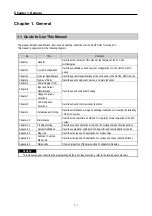
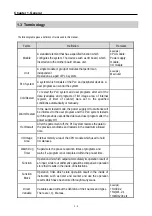
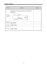
1.3 Terminology
The following table gives a definition of terms used in this manual.
Terms
Definition
Remarks
Module
A standard element that has a specified function which
configures the system. The devices such as I/O board, which
inserted onto the mother board or base unit.
Example)
CPU module,
Power supply
module,
I/O module
Unit
A single module or group of modules that perform an
independent
Operation as a part of PLC system.
Example)
Main unit
PLC System
A system which consists of the PLC and peripheral devices. A
user program can control the system.
Cold Restart
To restart the PLC system and user programs after all of the
data (variables and programs of I/O image area, of internal
register, of timer of counter) were set to the specified
conditions automatically or manually.
Warm Restart
In the warm restart mode, the power supply Off occurrence will
be informed to the user program and the PLC system restarts
with the previous user-defined data and user program after the
power supply Off.
Hot Restart
After the power went off, the PLC system restores the data to
the previous conditions and restarts in the maximum allowed
time.
I/O Image
Area
Internal memory area of the CPU module which used to hold
I/O statuses.
Watch Dog
Timer
Supervisors the pre-set execution times of programs and
warns if a program is not completed within the pre-set time.
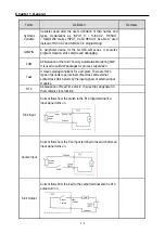
Function
Operation Unit which outputs immediately its operation result of
an input, while four arithmetic operations comparison operation
store their results in the inside of instructions.
Function
Block
Operation Units which store operation result in the inside of
instruction such as timer and counter and use the operation
results which have been stored through many scans.
Direct
Variable
Variables used without the definition of their names and types.
There are I, Q, M areas.
Example)
y
%IX0.0.2
y
%QW1.2.1
y
%MD1234 etc.
Содержание GLOFA G7M-DR20U
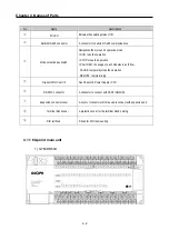
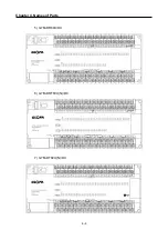
Страница 28: ...Chapter 4 Names of Parts 4 3 2 G7M DRT60U N 3 G7M DT60U N 4 G7M DT60U P...
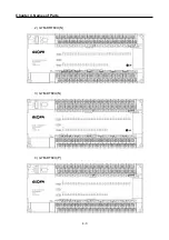
Страница 29: ...Chapter 4 Names of Parts 4 4 5 G7M DR60U DC 6 G7M DRT60U N DC 7 G7M DT60U N DC...
Страница 30: ...Chapter 4 Names of Parts 4 5 8 G7M DT60U P DC 4 1 2 40 point main unit 1 G7M DR40U 2 G7M DRT40U N...
Страница 31: ...Chapter 4 Names of Parts 4 6 3 G7M DT40U N 4 G7M DT40U P 5 G7M DR40U DC...
Страница 32: ...Chapter 4 Names of Parts 4 7 6 G7M DRT40U N DC 7 G7M DT40U N DC 8 G7M DT40U P DC...
Страница 33: ...Chapter 4 Names of Parts 4 8 4 1 3 30 point main unit 1 G7M DR30U 2 G7M DRT30U N 3 G7M DT30U N...
Страница 34: ...Chapter 4 Names of Parts 4 9 4 G7M DT30U P 5 G7M DR30U DC 6 G7M DRT30U N DC...
Страница 35: ...Chapter 4 Names of Parts 4 10 7 G7M DT30U N DC 8 G7M DT30U P DC 4 1 4 20 point main unit 1 G7M DR20U...
Страница 36: ...Chapter 4 Names of Parts 4 11 2 G7M DRT20U N 3 G7M DT20U N 4 G7M DT20U P...
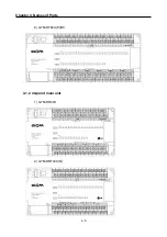
Страница 37: ...Chapter 4 Names of Parts 4 12 5 G7M DR20U DC 6 G7M DRT20U N DC 7 G7M DT20U N DC...
Страница 38: ...Chapter 4 Names of Parts 4 13 8 G7M DT20U P DC...
Страница 159: ...Chapter 7 Usage of Various Functions 7 52 c Program...
Страница 183: ...Chapter 7 Usage of Various Functions 7 76 c Program...
Страница 253: ...Chapter 8 Communication Functions 8 27 b When uses Ch 1 Built in RS 485...
Страница 355: ...Appendix 1 System Definitions App1 8 5 PID parameters 1 PID Auto Tuning Parameter 2 PID Parameter...
Страница 356: ...Appendix 1 System Definitions App1 9 6 Position Parameter...
Страница 357: ...Appendix 1 System Definitions App1 10 7 High Speed Counter Parameter...

