


Chapter 5. Power Supply / CPU
5-
8
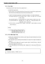
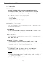
5.3.5 Timer processing
The CPU timer is an incremental timer, which increases its present value according to the measuring time. Three types
of On Delay Timer (TON), Off Delay Timer (TOF) and Pulse Timer (TP) are available. Its measuring range is 0.001 to
4,294,967,295 sec (1,193 hours) by 1 ms. For details, refer to “GLOFA-GM programming”.
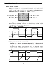
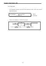
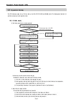
1) On Delay Timer
: Process Time Change and Contact On/Off
Timer Process time is newly changed when the timer function block is executed. When the process time reaches the
setting time (process time = setting time), the Timer output contact turns on.
On Delay Timer Timing Diagram is shown as below.
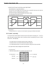
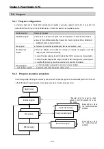
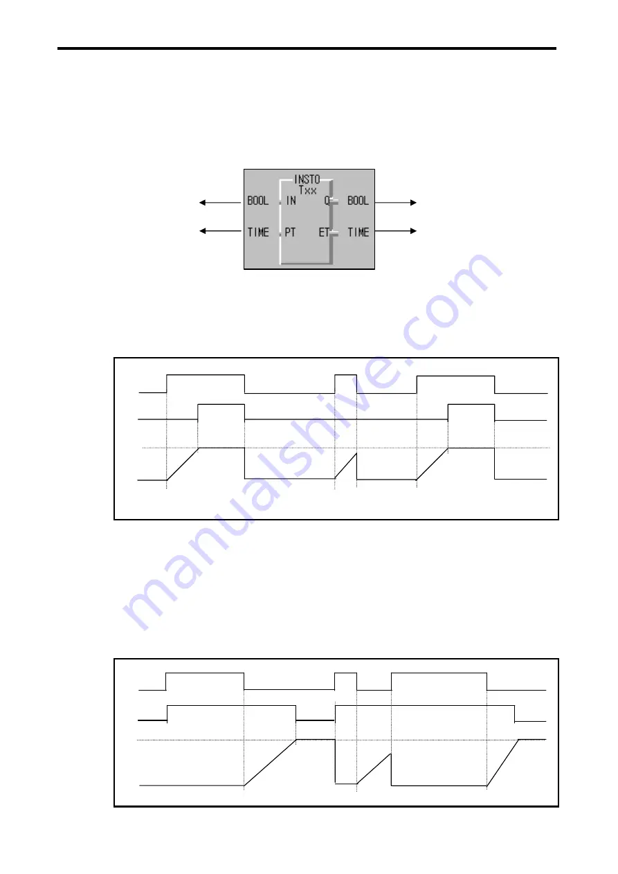
2) Off Delay Timer
: Process Time Change and Contact On/Off
y
If input condition turns on, timer output contact (Q) turns on. If input condition turns off, timer process time starts
increasing.
y
The process time is newly changed when the timer function block is executed. When the process time reaches the
setting time (process time = setting time), the contact (Q) turns off. The following diagram shows Off Delay Timer
Timing.
t0+PT
t0
t1
t2
t3
t4
t5
t5
t4+PT
t0
t1
t2
t3
t4
t5
IN
Q
PT
ET
t1+PT
t0
t1
t2
t3
t4
t5
t5+PT
t0
t1
t2
t3
t5
IN
Q
PT
ET
t1
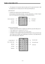
Elapsed time
Timer output contact
Timer trigger condition
Timer preset time
Содержание GLOFA G7M-DR20U
Страница 28: ...Chapter 4 Names of Parts 4 3 2 G7M DRT60U N 3 G7M DT60U N 4 G7M DT60U P...
Страница 29: ...Chapter 4 Names of Parts 4 4 5 G7M DR60U DC 6 G7M DRT60U N DC 7 G7M DT60U N DC...
Страница 30: ...Chapter 4 Names of Parts 4 5 8 G7M DT60U P DC 4 1 2 40 point main unit 1 G7M DR40U 2 G7M DRT40U N...
Страница 31: ...Chapter 4 Names of Parts 4 6 3 G7M DT40U N 4 G7M DT40U P 5 G7M DR40U DC...
Страница 32: ...Chapter 4 Names of Parts 4 7 6 G7M DRT40U N DC 7 G7M DT40U N DC 8 G7M DT40U P DC...
Страница 33: ...Chapter 4 Names of Parts 4 8 4 1 3 30 point main unit 1 G7M DR30U 2 G7M DRT30U N 3 G7M DT30U N...
Страница 34: ...Chapter 4 Names of Parts 4 9 4 G7M DT30U P 5 G7M DR30U DC 6 G7M DRT30U N DC...
Страница 35: ...Chapter 4 Names of Parts 4 10 7 G7M DT30U N DC 8 G7M DT30U P DC 4 1 4 20 point main unit 1 G7M DR20U...
Страница 36: ...Chapter 4 Names of Parts 4 11 2 G7M DRT20U N 3 G7M DT20U N 4 G7M DT20U P...
Страница 37: ...Chapter 4 Names of Parts 4 12 5 G7M DR20U DC 6 G7M DRT20U N DC 7 G7M DT20U N DC...
Страница 38: ...Chapter 4 Names of Parts 4 13 8 G7M DT20U P DC...
Страница 159: ...Chapter 7 Usage of Various Functions 7 52 c Program...
Страница 183: ...Chapter 7 Usage of Various Functions 7 76 c Program...
Страница 253: ...Chapter 8 Communication Functions 8 27 b When uses Ch 1 Built in RS 485...
Страница 355: ...Appendix 1 System Definitions App1 8 5 PID parameters 1 PID Auto Tuning Parameter 2 PID Parameter...
Страница 356: ...Appendix 1 System Definitions App1 9 6 Position Parameter...
Страница 357: ...Appendix 1 System Definitions App1 10 7 High Speed Counter Parameter...


