


Chapter 5. Power Supply / CPU
5-32
3) External device Ordinary-fault (warning) Processing
(1) If a warning of external device is detected and the corresponding flag of the system flag _ANC_WB[n] is set to on, the
flag will checked from the _ANC_WB[0] at the time that scan program finishes its execution. If an error is indicated on
the flag, it will be also indicated on the _ANNUN_WR of the representative system warning flag _CNF_WAR. External
device waning numbers will be written to from _ANC_WAR [0] to ANC.WAR [7] according to occurrence sequence.
(2) The user can know the cause of error by use of the GMWIN, and also by direct monitoring of the flags _ANC_WAR[n]
and _ANC_WB[n].
(3) If an external device waning is removed, that is, the elements of _ANC_WB [n] are released from warning, the
corresponding _ANC_WAR [n] will be automatically cleared, If all element flags are cleared, the flag _ANNUN_WR of
the system flag _CNF_WAR will be reset.
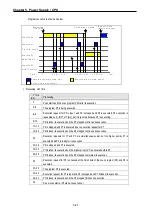
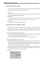
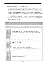
Example
Flag Status
Description
_ANNUN_WR
= 1
_ANC_WAR[0] = 10
_ANC_WAR[1] = 0
_ANC_WAR[2] = 0
_ANC_WAR[3] = 0
_ANC_WAR[4] = 0
_ANC_WAR[5] = 0
_ANC_WAR[6] = 0
_ANC_WAR[7] = 0
If the user program had detected a system fault and set _ANC_WB [10] to ON, the states of _
ANNUN_WR and _ANN_WAR [0..7] will be shown as left after the scan has been finished.
_ANNUN_WR
= 1
_ANC_WAR[0] = 10
_ANC_WAR[1] = 1
_ANC_WAR[2] = 2
_ANC_WAR[3] = 3
_ANC_WAR[4] = 15
_ANC_WAR[5] = 40
_ANC_WAR[6] = 50
_ANC_WAR[7] = 60
After the next scan has been finished, if the numbers 1, 2, 3,10,15 40, 50, 60 and 75 of
_ANC_WB [n] are tuned on _ANC_WAR [n] will be shown as left.
As the number 10 has turned on (has occurred) in the previous scan, though the number 10 h
as lower priority than the numbers 1, 2 and 3, it will be the lower element of _ANCWAR [n]. T
he _ANC_WB [75] is not indicated as it is turned on and the warning that occurred before has
written to the _ANC_WARIn1.
_ANNUN_WR
= 1
_ANC_WAR[0] = 1
_ANC_WAR[1] = 2
_ANC_WAR[2] = 3
_ANC_WAR[3] = 15
_ANC_WAR[4] = 40
_ANC_WAR[5] = 50
_ANC_WAR[6] = 60
_ANC_WAR[7] = 75
After the next scan has been finished, if the numbers 1, 2, 3, 10, 15, 40, 50, 60 and 75 of
_ANC_WB [n] are tuned on _ANC_WAR [n] will be shown as left.
The No. 10 warning has been released the content of _ANC_WAR [0] will be cleared and the c
ontents of _ANC_WAR [1..7] will shift into the lower elements. The content of _AN7_WAR [7] will
has been cleared by the shifting and the content of _AN7_WB [75] will be written to _ANC_WA
R[7].
_ANNUN_WR
= 0
_ANC_WAR[0] = 0
_ANC_WAR[1] = 0
_ANC_WAR[2] = 0
_ANC_WAR[3] = 0
_ANC_WAR[4] = 0
_ANC_WAR[5] = 0
_ANC_WAR[6] = 0
_ANC_WAR[7] = 0
If all warnings indicated on the _ANC_WB [n] are released during operation, the ANNUN_WR an
d _ANC_WAR [n] will be shown as left.
Содержание GLOFA G7M-DR20U
Страница 28: ...Chapter 4 Names of Parts 4 3 2 G7M DRT60U N 3 G7M DT60U N 4 G7M DT60U P...
Страница 29: ...Chapter 4 Names of Parts 4 4 5 G7M DR60U DC 6 G7M DRT60U N DC 7 G7M DT60U N DC...
Страница 30: ...Chapter 4 Names of Parts 4 5 8 G7M DT60U P DC 4 1 2 40 point main unit 1 G7M DR40U 2 G7M DRT40U N...
Страница 31: ...Chapter 4 Names of Parts 4 6 3 G7M DT40U N 4 G7M DT40U P 5 G7M DR40U DC...
Страница 32: ...Chapter 4 Names of Parts 4 7 6 G7M DRT40U N DC 7 G7M DT40U N DC 8 G7M DT40U P DC...
Страница 33: ...Chapter 4 Names of Parts 4 8 4 1 3 30 point main unit 1 G7M DR30U 2 G7M DRT30U N 3 G7M DT30U N...
Страница 34: ...Chapter 4 Names of Parts 4 9 4 G7M DT30U P 5 G7M DR30U DC 6 G7M DRT30U N DC...
Страница 35: ...Chapter 4 Names of Parts 4 10 7 G7M DT30U N DC 8 G7M DT30U P DC 4 1 4 20 point main unit 1 G7M DR20U...
Страница 36: ...Chapter 4 Names of Parts 4 11 2 G7M DRT20U N 3 G7M DT20U N 4 G7M DT20U P...
Страница 37: ...Chapter 4 Names of Parts 4 12 5 G7M DR20U DC 6 G7M DRT20U N DC 7 G7M DT20U N DC...
Страница 38: ...Chapter 4 Names of Parts 4 13 8 G7M DT20U P DC...
Страница 159: ...Chapter 7 Usage of Various Functions 7 52 c Program...
Страница 183: ...Chapter 7 Usage of Various Functions 7 76 c Program...
Страница 253: ...Chapter 8 Communication Functions 8 27 b When uses Ch 1 Built in RS 485...
Страница 355: ...Appendix 1 System Definitions App1 8 5 PID parameters 1 PID Auto Tuning Parameter 2 PID Parameter...
Страница 356: ...Appendix 1 System Definitions App1 9 6 Position Parameter...
Страница 357: ...Appendix 1 System Definitions App1 10 7 High Speed Counter Parameter...


