Page 202
Job Editor
Group 8
Release 2.02
JET3 Series
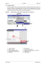
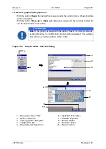
Start the graphic editor dialog box with the option
<Editors> - <Graphic-Editor>
(2)
and
(3)
.
The graphic editor provides a menu bar with the following entries:
File
Edit
Function
View
<Graphics>
are created and edited on the drawing area
(6)
.
The
<Coordinates>
(7)
indicate the current position on the drawing area.
The status bar for the current tool or command
(8)
indicates which tool is selected and
what is expected as next step.
The
<Cancel>
button
(9)
closes the dialog box. If the inputs have been not saved yet, a
confirmation prompt is displayed.
With the
<OK>
button
(10)
the graphic editor will be closed without further notice and all
changes will be aborted.
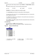
7.5.6.1 Edit tools
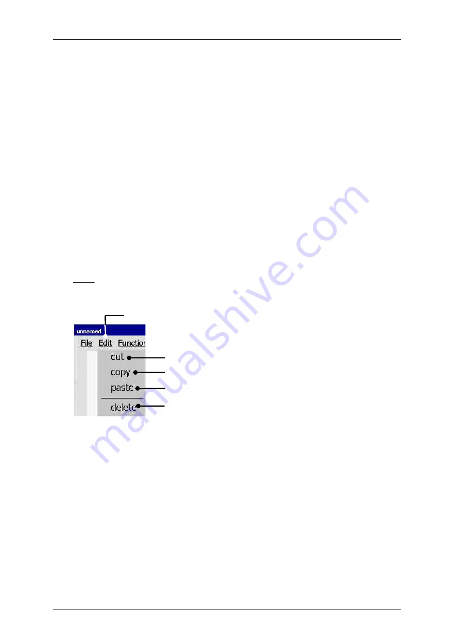
The drop-down menu
<Edit>
provides several tools.
Note:
The function of the tools corresponds to Windows™
-standard procedures.
Figure 95
Graphic editor (Edit tools)
1
–
Drop-down- menu <Edit>
3
–
Edit tool <copy>
5
–
Edit tool <delete>
2
–
Edit tool <cut>
4
–
Edit tool <paste>
1
2
3
4
5
Содержание JET3
Страница 1: ...Operating Manual V2 02 Please keep for future reference ...
Страница 2: ......
Страница 21: ...Group 2 Safety Page 19 JET3 Series Release 2 02 2 4 Safety sticker Figure 1 Safety sticker Safety sticker ...
Страница 380: ...Page 378 Appendix Connection Examples for the Interfaces Group 12 Release 2 02 JET3 Series Interface X3 Outputs ...
Страница 390: ...Page 388 Appendix List of illustrations Group 12 Release 2 02 JET3 Series 12 4 2 Print head SK 6 ...
Страница 391: ...Group 12 Appendix List of illustrations Page 389 JET3 Series Release 2 02 12 4 3 Print head SK 4 Option ...
Страница 392: ...Page 390 Appendix List of illustrations Group 12 Release 2 02 JET3 Series 12 4 4 Cabinet JET printer ...


