background image

®

This manual pertains to instruments with serial number 6830XXX
or higher.

8062A

True-rms Multimeter

Instruction Manual

PN 609153
May 1997 Rev.1, 1/00

© 1997, 2000 Fluke Corporation, All rights reserved. Printed in U.S.A.
All product names are trademarks of  their respective companies.

Содержание 8062A

Страница 1: ...ith serial number 6830XXX or higher 8062A True rms Multimeter Instruction Manual PN 609153 May 1997 Rev 1 1 00 1997 2000 Fluke Corporation All rights reserved Printed in U S A All product names are tr...

Страница 2: ...warranty period To obtain warranty service contact your nearest Fluke authorized service center or send the product with a description of the difficulty postage and insurance prepaid FOB Destination t...

Страница 3: ...power to the circuit under test before cutting unsoldering or breaking the circuit Small amounts of current can be dangerous Do not apply more than 500V rms between a terminal and earth ground Use cau...

Страница 4: ......

Страница 5: ...elf Test 2 10 2 11 AC DC Voltage V 2 11 2 12 True RMS Measurement 2 11 2 13 AC Coupled AC Measurements 2 12 2 14 Waveform Comparison and Conversion 2 13 2 15 High Impedance DC Voltage 2 14 2 16 AC DC...

Страница 6: ...4 13 4 15 Resistance Test 4 14 4 16 Continuity Test 4 15 4 17 Current Test 4 15 4 18 Diode Test 4 17 4 19 Calibration Adjustments 4 17 4 20 Troubleshooting 4 19 4 21 Self Tests 4 19 4 22 Ratio Self Te...

Страница 7: ...iii 6 11 AC Current Transformer Y8101 6 10 6 12 Safety Designed Test Lead Set TL70 6 11 6 13 Deluxe Test Lead Set Y8134 6 11 6 14 Slim Flex Test Lead Set Y8140 6 12 6 15 Cables and Adapters 6 12 7 Sch...

Страница 8: ...8062A Instruction Manual iv...

Страница 9: ...Divider 3 9 4 1 Required Test Equipment 4 4 4 2 Voltage Test 4 13 4 3 Resistance Test 4 15 4 4 Current Test 4 16 4 5 Switch Decoding Self Test 4 21 4 6 Troubleshooting Guide 4 22 4 7 Troubleshooting t...

Страница 10: ...8062A Instruction Manual vi...

Страница 11: ...ation 2 22 2 16 Continuity Operation 2 26 3 1 8062A Block Diagram 3 4 3 2 Analog Portion of the A D Converter 3 7 3 3 A D Measurement Cycle 3 7 3 4 Voltage Measurement 3 8 3 5 Current Measurement 3 10...

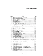
Страница 12: ...8062A Instruction Manual viii 7 5 A1 Main PCB Schematic Diagram 7 7 7 6 A3 RMS PCB Schematic Diagram 7 8...

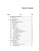
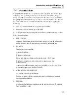
Страница 13: ...1 1 Chapter 1 Introduction and Specifications Contents Page 1 1 Introduction 1 3 1 2 Specifications 1 4...

Страница 14: ...8062A Instruction Manual 1 2...

Страница 15: ...ignal as an offset or relative reference value Other features include FUNCTIONS Standard DMM measurement functions such as ac and dc volts and ac and dc current as well as resistance continuity and di...

Страница 16: ...ter 6 Table 1 1 8062A Accessories Model No Description A81 C 90 80T 150C 80T 150F 80I 600 80K 6 80K 40 80J 10 83RF 85RF Battery Eliminator Vinyle Carrying Case Temperature Probe C Temperature Probe F...

Страница 17: ...Input Impedance 10 M shunted by 100 pf Normal Mode Noise Rejection 60 dB at 50 Hz or 60 Hz Common Mode Noise Rejection 120 dB at dc 90 dB at 50 Hz and 60 Hz 1 k imbalance Overload Protection 1000V dc...

Страница 18: ...V 200V 75 0 499 9V 100 mV 750V Not Specified 1 10 Not Specified 500 0 750 0V 2 10 Not specified for input 10 of range 1 kHz Input Impedance 10 M shunted by 100 pF Common Mode Noise Rejection 60 dB at...

Страница 19: ...cy of reading no of digits See table below Range Reso lution Accuracy Full scale Voltage Max Current Open Circuit Voltage 200 0 01 0 1 2 02 1 1 mA 4 8V 2 k 0 1 0 1 2 250 mV 150 A 20 k 1 0 1 2 15 A 1 5...

Страница 20: ...ime 50 s maximum 10 s typical Overload Protection 300V dc or rms ac Diode Test Range 2V Test Current 1 mA typical Accuracy 0 06 of reading 2 digits Specification applies for voltage measurement Respon...

Страница 21: ...9 99 mA 10 A 200 mA 1 5 10 1 10 200 0200 to 1999 9 mA 100 A 2000 mA Not Specified Not specified for input 10 of scale Burden Voltage 0 3V rms typical except 2000 mA range 0 9V rms typical Overload Pro...

Страница 22: ...d 9V battery NEDA 1604 or Fluke A 81 Battery Eliminator option available for 100 115 or 230V ac operation Battery Life Typically 170 hours with an alkaline battery BT appears on display when approxima...

Страница 23: ...put Limits 2 9 2 9 Operation 2 10 2 10 Power On Self Test 2 10 2 11 AC DC Voltage V 2 11 2 12 True RMS Measurement 2 11 2 13 AC Coupled AC Measurements 2 12 2 14 Waveform Comparison and Conversion 2 1...

Страница 24: ...8062A Instruction Manual 2 2...

Страница 25: ...ast three inches of shock absorbing material in the shipping container 2 3 Battery Installation or Replacement The 8062A is designed to operate on a single common inexpensive 9V battery NEDA 1604 You...

Страница 26: ...als if replacing the battery and attach the new battery 7 Slide the battery and its leads into the compartment and slide the cover into place WARNING TO AVOID SHOCK REMOVE INPUTS BEFORE OPENING CLOSE...

Страница 27: ...ld be in one of the two slots next to it The larger slot is for the American style fuse and the smaller slot is for the European style fuse either style fuse fits in the installation compartment If yo...

Страница 28: ...g paragraphs 2 6 Front Panel The front panel of the 8062A is designed to make function and range selection easy The symbols and colors on the panel indicate which switches to push or buttons to press...

Страница 29: ...nectors accept standard or safety designed banana plugs 5 COMMON Input Connector Protected test lead connector used as the low or common input for all measurements 6 A Input Connector Protected test l...

Страница 30: ...is placed automatically Symbols in the upper portion of the display indicate when one of the secondary functions is enabled The measurement units are indicated by the range switch that is pushed in Le...

Страница 31: ...ical shock and or instrument damage do not connect the common input terminal to any source more than 500 volts dc or rms ac above earth ground Table 2 2 Input Overload Limits Function Input Terminals...

Страница 32: ...turn on Figure 2 4 After about one or two seconds the display will go blank briefly before responding to switch selections If the LCD segments do not all turn on during the self test or if the instrum...

Страница 33: ...ect voltage function 4 Ensure all other switches are out 5 Connect the test leads as shown above 6 Heed the input overload limits Table 2 2 and connect the leads to the circuit being measured 7 Read t...

Страница 34: ...usoids but also for mixed frequencies modulated signals square waves sawtooths 10 duty cycle rectangular pulses etc 2 13 AC Coupled AC Measurements Input signals are ac coupled in the ac functions One...

Страница 35: ...meter measures 0 785V which amounts to a 5 6 error in the total rms measurement calculated from the ac and dc components AC Coupled Peak Voltages Display Readings DC and AC Input AC Component Only DC...

Страница 36: ...ffers a 1000 M typically 10 000 M input impedance dc voltage function which greatly reduces this error Figure 2 9 describes how to select the high input impedance dc voltage function the ac voltage fu...

Страница 37: ...2A 250V fuse in series with a 3A 600V fuse When a meter is placed in series with a circuit to measure current you may have to consider an error caused by the voltage drop across the meter in this case...

Страница 38: ...t A High 1 Select a range 2 Set AC DC switch out for DC in for AC 3 Push both switches at the same time to select current function 4 Ensure all other switches are out 5 Connect the test leads as shown...

Страница 39: ...n mA 35 Error Error in 100 x Eb Es Eb Error in A Eb x Im Es Eb Example ES 15V RI 100 k Im 148 51 A 14851 mA Eb 148 51 x 10 6 x 200 2 35 148 51 x 10 6 x 1000 35 148 56 mV Max error in 100 x 148 56 mV 1...

Страница 40: ...the circuit being measured is less than 250 mV The autoranging M ranges have enough voltage to turn on semiconductor junctions maximum 2 5V full scale but the current is very low 2 2 A maximum 2000mA...

Страница 41: ...tions in Chapter 1 2 18 Autoranging Megohms When the autoranging M range is selected the 8062A automatically selects the range appropriate for the measurement The measurement resolution decreases in t...

Страница 42: ...ative function with the autoranging k ranges is restricted to the autoranging k ranges Refer to the description of the relative function for more information The autoranging k has the same decrease in...

Страница 43: ...OL indicator provided that any resistance parallel to the junction is greater than 2 k 2000mA A A COMMON V S V S 200mA 200 200k 200 A DC AC 200mV 200 20mA 20 20k 2mA 2 2k 1000 DC 750 AC M REL 1000V DC...

Страница 44: ...measured value and the stored relative reference refer to Figure 2 15 2000mA A A COMMON V S V S 200mA 200 200k 200 A DC AC 200mV 200 20mA 20 20k 2mA 2 2k 1000 DC 750 AC M REL 1000V DC 750V AC MAX 2A M...

Страница 45: ...rload limits are not affected by the use of the relative function Another thing to be aware of when using relative reference is that the range of possible readings is still subject to the limits of th...

Страница 46: ...nd ac voltage or current diode and transistor matching diode test resistor matching and voltage deviation ac and dc voltage Note The use of the relative function with the autoranging k ranges is restr...

Страница 47: ...fixed ranges i e continuity is detected if resistance is less than 100 in the 200 range less than 1 k in the 2 k range etc The detection threshold is 100 for the autoranging k range and 100 M for the...

Страница 48: ...r switches are out 4 Press the button once to enable visible continuity Press the button again to enable audible continuity Press again to disable both 5 Connect the test leads as shown 6 Ensure that...

Страница 49: ...n the following step 2 AC VOLTAGE Select the ac voltage function and the 200V range Take note of the preceding warning and insert the probe tips into a standard wall socket The display should read the...

Страница 50: ...8062A Instruction Manual 2 28...

Страница 51: ...roduction 3 3 3 2 Functional Description 3 3 3 3 Microcomputer 3 3 3 4 Measurement Acquisition Chip MAC 3 5 3 5 A D Converter Cycle 3 5 3 6 Voltage Measurement 3 8 3 7 Current Measurement 3 9 3 8 Resi...

Страница 52: ...8062A Instruction Manual 3 2...

Страница 53: ...MAC also controls the power supply and the continuity tone generator The microcomputer and the MAC communicate through a four bit bidirectional bus and four control lines Both components are describe...

Страница 54: ...e MAC refer to Chapter 2 for operating instructions While the LCD segments are on a minimum of 1 6 seconds the microcomputer exercises the bus and checks the internal registers in the MAC to make sure...

Страница 55: ...tone by supplying a square wave to the external piezoelectic transducer 3 5 A D Converter Cycle The heart of the MAC is the dual slope a d converter A block diagram of the analog portion of the a d c...

Страница 56: ...he buffer amplifier loop and appear at the comparator output as an error voltage To compensate for this error the error is impressed across the AZ capacitor where it is stored for the remainder of the...

Страница 57: ...ero voltage The count is proportional to the unknown input voltage and is placed on the display by the microcomputer If during the read period the counter counts up to the maximum number of counts for...

Страница 58: ...round to perform the input signal division The dc input voltages for all ranges are divided by the appropriate factor of 10 to produce a proportional dc signal which is then filtered and applied to th...

Страница 59: ...20V 200V 750V 1 1 1 10 1 100 1 1000 1 1000 0 to 200 mV 0 to 200 mV 0 to 200 mV 0 to 200 mV 0 to 2V 0 75V max input Integrator gain in a d converter reduced by factor of 10 3 7 Current Measurement Cur...

Страница 60: ...across each of them Since the voltage drop across the reference resistor and the value of the reference resistor are known the value of the second resistor can be determined Input protection during re...

Страница 61: ...ies the microcomputer which turns on the visible indicator the full length bar across the top of the display If the audible indicator is enabled the continuity logic enables the tone generator The dir...

Страница 62: ...8062A Instruction Manual 3 12...

Страница 63: ...nd Microcomputer PCB Disassembly and Assembly 4 8 4 9 Backup Fuse Replacement 4 11 4 10 Cleaning 4 11 4 11 Performance Tests 4 12 4 12 Initial Procedure 4 12 4 13 Microcomputer and Display Test 4 12 4...

Страница 64: ...8062A Instruction Manual 4 2...

Страница 65: ...djustments is listed in Table 4 1 Test equipment with equivalent specifications may also be used 4 2 Service Information The 8062A is warranted for a period of one year upon shipment of the instrument...

Страница 66: ...z 0 to 200V 0 25 50 kHz to 100 kHz 0 to 2 0V 0 75 Resistance 100 to 10 0 M 0 025 Fluke 5700A DC Current 0 to 2000 mA 0 075 AC Current 20 Hz to 3 kHz 0 to 2000 mA 0 18 Frequency 25 mV to 200 mV 100 Hz...

Страница 67: ...nectors Wear static ground straps Use conductive foam to store components Remove all plastic vinyl and styrofoam from the work area Use a grounded temperature regulated soldering iron 4 5 Disassembly...

Страница 68: ...f the case 3 Turn the instrument face up and grasp the top cover at both sides of the input connectors Then pull the top cover from the unit The backup fuse and the calibration adjustments are now acc...

Страница 69: ...the side Backup Fuse F2 dy32c eps Figure 4 1 CALIBRATION AND BACKUP FUSE F2 ACCESS 4 7 Main PCB Access Use the following procedure to gain access to the main pcb 1 Remove the screw in the center of th...

Страница 70: ...insulator If the ac shield is attached to the main pcb before the main pcb is in the case the spring may fold across the insulator and not be in proper position to make the electrical connection b Be...

Страница 71: ...mputer Interconnect Insert edge under retainer LCD Plate Do not remove LCD Bracket LCD Support Display Lens Serial effectivity 3995000 Gasket Align then push down and snap into place CAUTION Use tweez...

Страница 72: ...sembled take care not to press down on the display lens because pressure could damage the LCD To disassemble the LCD use your thumbnails and push on the corners of the LCD display gasket and display l...

Страница 73: ...Backup Fuse Replacement Use the following procedure to replace the backup fuse F2 1 Remove the top cover by following the precautions given previously for the calibration and backup fuse access 2 Use...

Страница 74: ...edure For any of these tests make sure you do the following 1 Allow the temperature of the UUT to stabilize in a test environment with an ambient temperature of 23 5 C 73 9 F and a relative humidity o...

Страница 75: ...189 90 to 190 11 189 89 to 190 11 1 8989 to 1 9011 18 985 to 19 015 189 85 to 190 15 999 1 to 1000 9 7 8 AC Voltage 200 mV 100 00 mV rms 200 Hz 20 kHz 99 40 to 100 60 98 60 to 101 40 9 10 11 12 13 14...

Страница 76: ...UUT and the DMM Calibrator as shown in Figure 4 4 2 Select the resistance function and follow the steps 1 through 7 as listed in Table 4 3 For each step select the UUT function and range as indicated...

Страница 77: ...range Press the button once The symbol should appear on the display 3 Apply a resistance of 100 0 The long bar across the top of the display should appear on the display immediately A reading of 0997...

Страница 78: ...1000V DC 750V AC MAX 2A MAX 500V MAX DMM Calibrator HI UUT LO dy36f eps Figure 4 5 Equipment Connection for Current Test Table 4 4 Current Test Step Function Range Input Signal Display Level Freq Lim...

Страница 79: ...istance After you have completed the calibration adjustments we recommend that you complete the performance tests to verify proper operation In the following procedure the 8062A that is being adjusted...

Страница 80: ...gram the DMM Calibrator for an input of 190 00 mV dc Adjust R8 for a display reading between 189 99 and 190 01 8 On the UUT select the ac voltage function and the 200 mV range Turn R18 full CW and tur...

Страница 81: ...unction as follows 4 22 Ratio Self Test The ratio self test is an operating mode of the 8062A in which the reference voltage for the a d converter is applied to the a d converter during both the integ...

Страница 82: ...o know that the microcomputer scans the switches in order from SW5 to SW8 there is no input for switch SW4 the default range The microcomputer assumes the first range switch detected as being pushed i...

Страница 83: ...y discrepancies in performance Then locate the test symptom and possible cause of malfunction in Table 4 6 When several possible causes of malfunction are listed they are listed in order beginning wit...

Страница 84: ...and diode test source to stop working However it will also eliminate any power supply leakages that might be affecting the input circuitry Since the input protection input divider and ohms reference...

Страница 85: ...can then check the ac converter diode test source VR2 U4 and the power supply circuitry Voltage Test DC Gross error constant reading of 0 00 or OL Perform ratio self test in dc volts If count is good...

Страница 86: ...3 Vss J7 Com J12 Vdd Resistance Test All ranges incorrect Ohms source voltage inadequate using a voltmeter in the 2V or 20V range measure ohms source voltage between TP11 and common Refer to Table 4 7...

Страница 87: ...t readings off U1 Continuity Test No response Select switch decoding self test check for proper function decoding and also confirm that the continuity comparator responds R31 S1A No tone Q6 R4 LS1 Che...

Страница 88: ...tude appropriately A DMM with a 10 M input impedance will read approximately 1 9V in the M range Table 4 8 U3 MAC Pin Descriptions Pin No Mnemonic Description 1 Tone 2 66 kHz square wave to tone gener...

Страница 89: ...the U3 and U5 digital power supply Output of the U3 and U5 digital power supply 24 25 26 27 AD0 AD1 AD2 AD3 Four bit parallel data bus between U3 and U5 During the first part of a data transfer opera...

Страница 90: ...8062A Instruction Manual 4 28...

Страница 91: ...5 1 Chapter 5 List of Replaceable Parts Contents Page 5 1 Introduction 5 3 5 2 How to Obtain Parts 5 3 5 3 Manual Status Information 5 4 5 4 Newer Instruments 5 4 5 5 Service Centers 5 4...

Страница 92: ...8062A Instruction Manual 5 2...

Страница 93: ...using the manufacturers part number or from the Fluke Corporation and its authorized representatives by using the part number under the heading FLUKE STOCK NO In the U S order directly from the Fluke...

Страница 94: ...ble is included with the manual 5 5 Service Centers To locate an authorized service center call Fluke using any of the phone numbers listed below or visit us on the World Wide Web www fluke com 1 800...

Страница 95: ...2 H2 SCREW PH P THD FORM STL 7 19 750 447953 3 H3 SCREW FH P STL 6 32 375 837682 1 H4 WASHER COUNTER SUNK STAINLESS STEEL 614529 1 MP1 BAIL STAND MED PEWTER 616961 1 MP2 BRACKET LCD MOUNTING 795112 1...

Страница 96: ...AD ASSY TL70A 855820 1 MP40 BUTTON FUNC SW DK PEWTER MODIFIED 930347 1 S10 SWITCH ELASTOMERIC 2 POSITION 604827 1 TM1 8062A INSTRUCTION MANUAL 609153 1 TM2 8062A OPERATOR GUIDE 632703 1 TM3 DMM ACCESS...

Страница 97: ...List of Replaceable Parts 5 5 7 Test Button Up 1 of 2 dy37c eps Figure 5 1 8062A Final Assembly...

Страница 98: ...8062A Instruction Manual 5 8 Test Button Up 2 of 2 dy38c eps Figure 5 1 8062A Final Assembly cont...

Страница 99: ...U 831982 2 C12 C21 CAP AL 10UF 20 16V SOLV PROOF 602326 2 C13 C30 C37 CAP CER 0 01UF 20 50V X7R 816249 3 C16 CAP TA 1UF 20 35V 161919 1 C17 CAP POLYES 0 01UF 10 1000V 822361 1 C22 CAP POLYPR 0 1UF 10...

Страница 100: ...R15 RES VAR CERM 3K 20 0 3W 689627 1 R16 RES MF 383K 1 0 125W 100PPM 288498 1 R18 RES VAR CERM 100 20 0 3W 614057 1 R20 RES CC 220K 10 1W 109652 1 R22 RES JUMPER 0 02 0 25W 682575 1 R31 RES CF 10 5 0...

Страница 101: ...C 18 U 513937 1 Z1 RNET MF POLY SIP 8060 HI V DIVIDER 539213 1 Z2 RES WW NET TOL MATCHED 435727 1 Z3 RNET MF POLY SIP 8060 LO V DIVIDER 611467 1 Z4 RES CERM NET TOL TC MATCHED 614164 1 Z5 RES CERM NET...

Страница 102: ...8062A Instruction Manual 5 12 8062A 4031 iv39c eps Figure 5 2 A1 Main PCB Assembly...

Страница 103: ...F 10K 0 1 125W 25PPM 1206 106366 2 R3 RES MF 8 45K 0 1 0 125W 25PPM 1206 689528 1 R4 R15 R16 RES CERM 15K 1 125W 100PPM 1206 769810 3 R5 R6 RES CERM 200K 1 0 1W 100PPM 0805 928882 2 R13 RES CERM 10K 1...

Страница 104: ...8062A Instruction Manual 5 14 Circuit 1 Ref Des View Circuit 2 Ref Des View 8060A 4003M dy60f eps Figure 5 3 A3 RMS PCB Assembly...

Страница 105: ...6 5 High Voltage Probe 80K 6 6 6 6 6 High Voltage Probe 80K 40 6 7 6 7 High Frequency Probe 83RF 6 7 6 8 High Frequency Probe 85RF 6 8 6 9 Current Shunt 80J 10 6 9 6 10 AC DC Current Probe Y8100 6 9 6...

Страница 106: ...8062A Instruction Manual 6 2...

Страница 107: ...well as convenient storage locations for test leads operator guide and other small accessories A finger or belt loop is included on the case as a carrying convenience 6 3 Temperature Probes 80T 150C...

Страница 108: ...8062A Instruction Manual 6 4 dy55c eps Figure 6 1 Accessories...

Страница 109: ...Accessory Information Temperature Probes 80T 150C and 80T 150F 6 6 5 dy56c eps Figure 6 1 Accessories cont...

Страница 110: ...rrent measurement RANGE 1 to 600A ac ACCURACY 3 FREQUENCY RESPONSE 30 Hz to 1 kHz 10 kHz typical DIVISION RATIO 1000 1 INSULATION 5 kV MAXIMUM CONDUCTOR SIZE 2 inch diameter 6 5 High Voltage Probe 80K...

Страница 111: ...rms ac INPUT RESISTANCE 1000 M DIVISION RATIO 1000 1 ACCURACY DC OVERALL 20 kV to 30 kV 2 calibrated at 25 kV UPPER LIMIT Changes linearly from 2 at 30 kV to 4 at 40 kV LOWER LIMIT Changes linearly fr...

Страница 112: ...nectors 6 8 High Frequency Probe 85RF The Model 85RF High Frequency Probe allows measurements over a frequency range of 100 kHz to 500 MHz from 25V to 30V rms It operates in conjunction with the instr...

Страница 113: ...20 amps for periods not exceeding one minute dc to 10 kHz at an accuracy of 0 25 in excess of the voltmeter accuracy SHUNT 10 amps at 100 mV ACCURACY 18 C to 28 C DC to 10 kHz 10 kHz to 100 kHz 0 25 R...

Страница 114: ...MMENDED LOAD 3 0 k TEMPERATURE RANGE 15 C to 35 C for specified accuracy 10 C to 50 C storage and operation at reduced accuracy HEATING LIMITATION Prolonged operation above 200A ac or 1 kHz can cause...

Страница 115: ...TL70 Test Lead Set includes one red and one black test lead Each probe has an anti slip shoulder near the test tip and is connected to the multimeter via a safety designed shrouded banana connector T...

Страница 116: ...Cables and Adapters A variety of cables and adapters are available for use with the 8062A and are listed in Table 6 1 Table 6 1 Cables and BNC Banana Phone and Phono Plug Adapters Model Description Y9...

Страница 117: ...grams Figure Title Page 7 1 A1 Main PCB Component Locations TopView 7 3 7 2 Test Point Locations 7 4 7 3 A D Measurement Cycle 7 5 7 4 Switch Detail 7 5 7 5 A1 Main PCB Schematic Diagram 7 7 7 6 A3 RM...

Страница 118: ...8062A Instruction Manual 7 2...

Страница 119: ...Schematic Diagrams 7 7 3 8062A 4031 iv39c eps Figure 7 1 A1 Main PCB Component Locations TopView...

Страница 120: ...345V Supply ground U5 57 scope trigger A D cycle VDD 5 2V supply on uC pcb VDG digital supply 3 15V ref to VDD TP7 uC clock 40 kHz nominal Freq Continuity comparator output Ohms Source Output TP10 Top...

Страница 121: ...dings halfscale fullscale and overrange refer to Figure 4 3 and Section 4 for theory of operation The three overlaid traces shown were made on a storage oscilloscope connected to U3 17 and triggered b...

Страница 122: ...8062A Instruction Manual 7 6...

Страница 123: ...8062A Instruction Manual 7 7 8062A 1201 iu46c eps Figure 7 5 A1 Main PCB Schmatic Diagram...

Страница 124: ...8062A Instruction Manual 7 8 8060A 1003 iu61f eps Figure 7 6 A3 RMS PCB Schmatic Diagram...

Отзывы: