3-23
Cisco Wireless LAN Controller Configuration Guide
OL-17037-01
Chapter 3 Configuring Ports and Interfaces
Configuring Ports
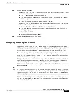
Step 5
Perform one of the following:
•
Follow these steps if you want to choose a specific client device that will mirror its traffic to the port
you selected on the controller:
a.
Click
Wireless
>
Clients
to open the Clients page.
b.
Click the MAC address of the client for which you want to enable mirror mode. The Clients >
Detail page appears.
c.
Under Client Details, set the Mirror Mode parameter to
Enable
.
•
Follow these steps if you want to choose an access point that will mirror its traffic to the port you
selected on the controller:
a.
Click
Wireless
>
Access Points
>
All APs
to open the All APs page.
b.
Click the name of the access point for which you want to enable mirror mode. The All APs >
Details page appears.
c.
Click the
Advanced
tab.
d.
Set the Mirror Mode parameter to
Enable
.
Step 6
Click
Save Configuration
to save your changes.
Configuring Spanning Tree Protocol
Spanning Tree Protocol (STP) is a Layer 2 link management protocol that provides path redundancy
while preventing loops in the network. For a Layer 2 Ethernet network to function properly, only one
active path can exist between any two network devices. STP allows only one active path at a time
between network devices but establishes redundant links as a backup if the initial link should fail.
The spanning-tree algorithm calculates the best loop-free path throughout a Layer 2 network.
Infrastructure devices such as controllers and switches send and receive spanning-tree frames, called
bridge protocol data units (BPDUs), at regular intervals. The devices do not forward these frames but
use them to construct a loop-free path.
Multiple active paths among end stations cause loops in the network. If a loop exists in the network, end
stations might receive duplicate messages. Infrastructure devices might also learn end-station MAC
addresses on multiple Layer 2 interfaces. These conditions result in an unstable network.
STP defines a tree with a root bridge and a loop-free path from the root to all infrastructure devices in
the Layer 2 network.
Note
STP discussions use the term
root
to describe two concepts: the controller on the network that serves as
a central point in the spanning tree is called the
root bridge
, and the port on each controller that provides
the most efficient path to the root bridge is called the
root port
. The root bridge in the spanning tree is
called the
spanning-tree root
.
STP forces redundant data paths into a standby (blocked) state. If a network segment in the spanning tree
fails and a redundant path exists, the spanning-tree algorithm recalculates the spanning-tree topology
and activates the standby path.

