


11-17
Cisco Wireless LAN Controller Configuration Guide
OL-17037-01
Chapter 11 Configuring Radio Resource ManagementWireless Device Access
Configuring RRM
Note
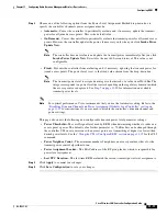
If both the number and percentage of failed packets exceed the values configured for Failed
Packet Count and Failed Packet Percentage (configurable through the controller CLI; see
) for a 5-second period, the client is considered to be in a pre-alarm condition. The
controller uses this information to distinguish between real and false coverage holes. False
positives are generally due to the poor roaming logic implemented on most clients. A coverage
hole is detected if both the number and percentage of failed clients meet or exceed the values
entered in the Min Failed Client Count per AP and Coverage Exception Level per AP fields over
a 90-second period. The controller determines if the coverage hole can be corrected and, if
appropriate, mitigates the coverage hole by increasing the transmit power level for that specific
access point.
Step 8
Click
Apply
to commit your changes.
Step 9
To re-enable the 802.11a or 802.11b/g network, follow these steps:
a.
Click
Wireless
>
802.11a/n
or
802.11b/g/n
>
Network
to open the 802.11a (or 802.11b/g) Global
Parameters page.
b.
Check the
802.11a
(or
802.11b/g
)
Network Status
check box.
c.
Click
Apply
to commit your changes.
Step 10
Click
Save Configuration
to save your changes.
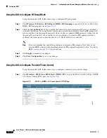
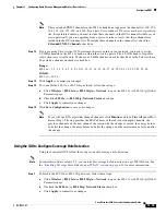
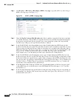
Using the GUI to Configure RRM Profile Thresholds, Monitoring Channels, and Monitor Intervals
Using the controller GUI, follow these steps to configure RRM profile thresholds, monitoring channels,
and monitor intervals.
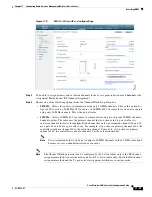
Step 1
Click
Wireless
>
802.11a/n
or
802.11b/g/n
>
RRM
>
General
to open the 802.11a (or 802.11b/g) >
RRM > General page (see
).


