


<Appendix 8 Explosion Protected Type Instrument>
App.8-9
IM 11Y01D01-01EN
l
TDLS8000-S2 (ATEX Certification)
(1) Technical Data
• Applicable standards
EN 60079-0: 2012+A11:2013
EN 60079-15: 2010
EN 60079-28: 2007
EN 60079-28: 2015
EN 60079-31: 2014
• Ratings
II 3(1) G Ex nA nC [op is T6 Ga] IIC T5 Gc
II 2 D Ex tb IIIC T100 °C Db
• Enclosure
IP66 (In accordance with EN 60529)
• Specific condition of use
Precautions shall be taken to minimize the risk from electrostatic discharge or propagating
brush discharge of painted parts of the enclosure.
In case of the enclosure of TDLS8000 with paint layers, if it is mounted in an area where
the use of category 2D equipment is required, it shall be installed in such a way that the risk
from electrostatic discharges and propagating brush discharges caused by rapid flow of
dust is avoided.
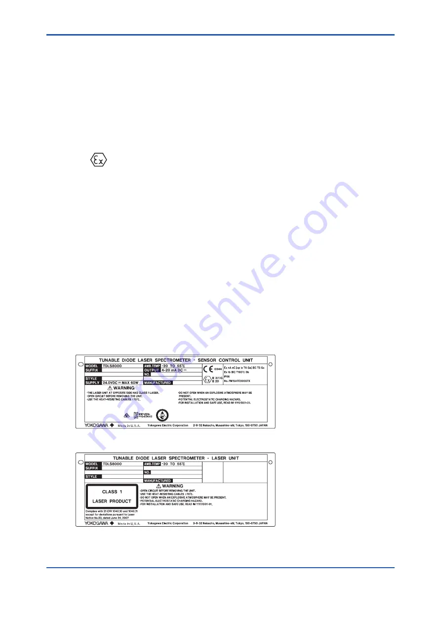
(2) Name Plate
MODEL:
Specified model code
AMB.TEMP:
Specified ambient temperature range
SUFFIX:
Specified suffix code
OUTPUT:
Specified analog output range
NO.:
Serial number
STYLE:
Specified style code
SUPPLY:
Specified supply voltage and wattage
MANUFACTURED: Month and year of production
Main Name Plate (Sensor Control Unit side)
Sub Name Plate (Laser Unit side)
3rd Edition: Jun. 10, 2016-00
Summary of Contents for TDLS8000
Page 10: ...ix IM 11Y01D01 01EN LT LV PL EST SLO H BG RO M CZ SK 3rd Edition Jun 10 2016 00...
Page 25: ...Blank Page...
Page 45: ...Blank Page...
Page 115: ...Blank Page...
Page 151: ...Blank Page...
Page 231: ...Blank Page...
Page 239: ...Blank Page...
Page 243: ...Blank Page...
Page 261: ...Blank Page...
Page 303: ......
Page 305: ......
Page 307: ......
Page 309: ......
Page 311: ......
Page 313: ...Blank Page...


