03-914978-00:1
45
Chemical Ionization Options
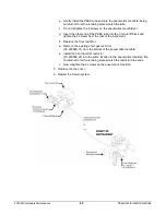
1. Loosen the 2 screws that attach the liquid CI inlet L-bracket to the back of the
instrument. Also, loosen the 2 screws that attach the L-bracket to the liquid
CI inlet block.
2. Remove the liquid CI restrictor end that inserts into the back of the instrument;
rotate the restrictor out of the way.
3. Install the long CI gas restrictor (03-930597-01) between the gas supply and the
CI shutoff block, through the L-bracket.
4. Tighten all screws.
5. It is not necessary to replace the front liquid CI restrictor (03-930024-01) with the
short gas restrictor (03-930596-01). Reduce the gas pressure to 5 psi at the
supply to return to normal gas CI operating conditions.
Installing and Using the Multiple CI Module
The MCI Module operates essentially as a triplicate of the Standard CI option in
the Saturn
®
2000. Examine the Channel A section of the following schematic
diagram of the module. A liquid (or optional gas) sample is chosen for Channel A.
Two solenoid valves intervene between the liquid sample and the main gas line
to the Saturn MS on the right of the diagram. These valves are always controlled
together — both ON or both OFF. The control of the Valve States is from the
External Events (Valve States) section of the GC. The valves may be turned ON
and OFF either from the GC front panel or from the GC section of the GC/MS
Method. The restrictors between the two solenoid valves for each Channel have
been chosen to provide an adequate and adjustable flow of acetonitrile,
methanol, methane, or isobutane flow when the MCI Module is set up according
to instructions. A third, adjustable, restrictor is the Needle Valve in the line
connected to the foreline Pump.
The guiding principle in the design of CI flow is to provide an adequate flow of
reagent vapor, which is adjustably split toward the foreline pump and the ion trap.
Closing the 15-turn needle valve clockwise (CW) directs more flow to the ion
trap; counterclockwise adjustment sends a higher proportion of the flow to the
foreline pump. This two-directional flow pattern allows the foreline pump to
rapidly clear residual CI reagent from the MCI Module when the Main CI Solenoid
in the Saturn 2000 (lower right of the schematic) is turned off in Manual Control.
It also allows rapid changeover of flows from one Channel to another.


