03-914978-00:1
23
Functional Description
Ion Trap Electrodes
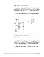
The ion trap assembly contains three stainless steel electrodes:
•
Filament endcap electrode
•
Exit endcap electrode
•
RF ring electrode
The filament endcap, exit endcap, and RF-ring electrodes have hyperbolic inner
surfaces. Together, these electrodes form a cavity in which ionization,
fragmentation, storage, and mass analysis take place.
Energetic electrons enter the ion trap cavity through the filament endcap via the
electron gate.
There are seven holes in the center of the exit endcap electrode. Sample ions
produced in the ion trap are ejected through these holes into the electron
multiplier.
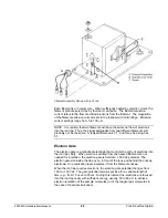
Two identical quartz or silica-coated spacers separate the central ring electrode
from the filament and exit endcap. The trap oven and its clamping plate hold the
electrodes and spacers in place. A cutout is provided in the quartz spacers and
in the exit endcap to allow the transfer line to enter the ion trap.
The RF generator assembly provides high voltage RF that is applied to the RF
ring electrode.
Under the proper RF voltage, the ion trap electrodes create a three-dimensional,
hyperbolic electric field. This field is capable of trapping the ions in stable,
aperiodic orbits. As the RF voltage increases, however, the ion trajectories
become unstable in increasing order of mass per charge. The ion trap ejects the
ions and sends them to an electron multiplier for detection.
During mass analysis, a supplementary RF voltage of 485 kHz is applied to the
filament and exit endcaps. This voltage, termed the axial modulation voltage,
improves spectral mass resolution and analytical sensitivity. Other voltages may
be applied between the endcaps to implement such options as SECI and
MS/MS. For further details, see the Saturn Method Editor for description of scan
functions.
Electron Multiplier
The electron multiplier is positioned at the exit endcap electrode. It mounts in a
pre-aligned position on a protective metal clip that you can easily remove to
replace the multiplier. The multiplier detects positive ions as the ion trap ejects
them through the holes in the exit endcap electrode. The continuous-dynode
electron multiplier consists of a lead-oxide/glass, funnel-like resistor. A negative
voltage of between -800 and -3000V is applied to the front end of the electron
multiplier, referred to as the cathode. The back end of the cathode is held at
ground potential, and is referred to as the anode.


