03-914978-00:1
41
Chemical Ionization Options
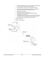
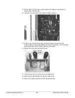
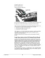
d. Loosely attach the Liquid CI Inlet assembly to the back of the instrument
via the L-bracket with the screw that was removed.
e. Rotate the Liquid CI Inlet assembly out of the way to remove the
remaining screw.
f. Rotate the Liquid CI Inlet assembly back into position and loosely attach
the liquid CI inlet assembly with the remaining long screw (12-222006-
25).
g. Re-insert the liquid CI restrictor tube through the L-bracket into the back
of the instrument. The restrictor tube must be inserted far enough to
engage the O-ring in the CI shutoff block.
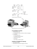
A
Inlet Block (03-930023-01)
E
Reservoir Cover (03-930026-
01)
B
Viton O-ring (03-930109-07)
F
Restrictor (03-930024-01)
C
O-ring Retainer (03-930025-01) G
L-Bracket (03-930027-01)
D
Reservoir Bulb, same as Cal
Gas Chamber (03-920270-00)
H
Viton O-Ring (03-930109-04)
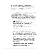
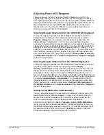
3. Replace long restrictor (03-930597-01) with 1/8" OD PEEK tubing (03-930037-
01).
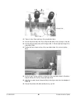
a. With the liquid CI inlet mounting screws still loose, pull out the long
restrictor tube from the CI shutoff block.
b. Loosen the 4 screws on the top of the pneumatics manifold (at the front
of the instrument).
c. Pull out the long restrictor tube from the bottom of the pneumatics
manifold. Carefully pull the tube out of the front of the instrument. Save
this long restrictor for use with pressurized gases such as methane.
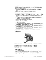
d. Feed the PEEK tube (03-930037-01) into position, starting from the front
of the instrument (occupies roughly the same space as the long restrictor
tube).

