03-914978-00:1
51
Chemical Ionization Options
5
. Unplug the power cord.
6
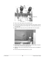
. Remove the top covers.
7
. Remove the high voltage cover.
8
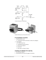
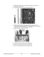
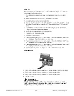
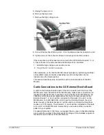
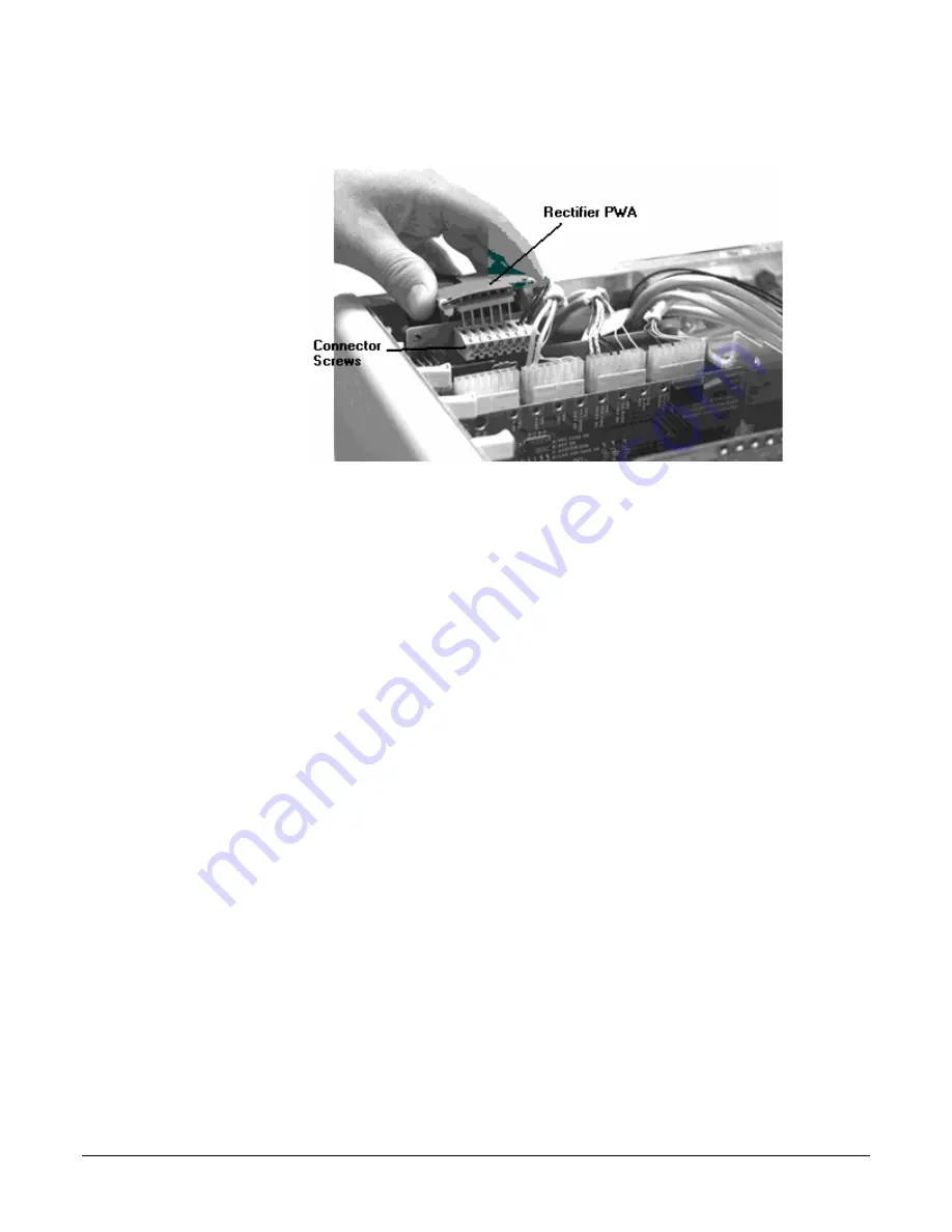
. Connect the Rectifier PWA to pins 3 - 8 on the External Events board in the GC.
9
. Tighten all six of the connector screws to ensure good electrical contact.
If there are other electrical devices connected to the GC External Events 2, 3, or
4, they will have to be disconnected while Multiple CI is connected.
1. Install the high voltage cover and top covers.
2. Plug in the GC and turn on power.
After installation, verify that the MCI Module is leak-tight by performing Air/Water
and available pressure checks (depending upon the configuration of your
instrument) on the Saturn system.
This section describes setup, acquisitions with, and maintenance of the MCI
Module.
Cable Connections to the GC External Events Board
A cable to the External Events board of the GC connects each Channel of the
MCI Module. Upon installation of the MCI Module, make these connections and
identify the External Events connected to each Channel of the MCI Module. For
3800 GCs which have seven External Events, the most likely scenario is that
External Events 1, 2, and 3 will be connected to Channels A, B, and C on the
MCI Module. For 3400/3600 GCs, which have four External Events, the most
likely scenario is that External Event 1 will be used to control split and splitless
modes in a 1078 injector. Then Events 2, 3, and 4 will be connected to Channels
A, B, and C on the MCI Module. Assure that you are aware of the connection
pattern for your system.
For easiest reference in the future, we suggest that you use an erasable marking
pen to write the number of the External Event along with the installed reagent on
the label for each Channel of the MCI Module.


