03-914978-00:1
29
Functional Description
•
The electron energy control circuits, which controls the dc bias on both
the ion trap and ion gauge filaments.
•
The diagnostic multiplexer circuit, which routes the voltage output of
various components, and circuits on the power control board to the
SAP/Wave board. You can access these voltage outputs through the
diagnostic pages.
•
Mounted on the top edge of the power board are 15 monitor LEDs.
When illuminated, these lights indicate that the voltages of the various
circuits on the power board are at their proper levels, and that there are
no faults. During normal operation all LEDs except the
±
180 volts should
be on. The
±
180 volts only turns on when the filaments are on.
The RF Generator Assembly
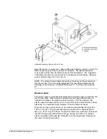
The RF generator assembly consists of an RF generator circuit board, an RF
detector circuit board, and the RF coil. A shielded housing beneath the vacuum
manifold encloses the coil and RF detector circuit board. The RF generator
circuit board is attached to the back of the shielded housing.
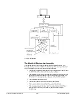
The RF generator circuit board receives an analog signal from the SAP/Wave
circuit board that is proportional to the current mass position in the scan, which is
in turn proportional to the desired RF voltage applied to the ion trap. The RF
detector circuit board sends a signal proportional to the actual amount of RF
voltage applied to the ion trap to the RF generator board. The RF generator
board compares the desired and actual amount of the RF voltage and adjusts the
gain of an RF amplifier to cause the actual RF voltage to equal the desired RF
voltage. Since the high voltage required at the ion trap exceeds the capabilities
of conventional electronic amplifiers, a resonant LC circuit consisting of the RF
coil and the ion trap capacitance is used. At resonance, the RF voltage at the ion
trap end of the coil is about 100 times that at the RF generator circuit end of the
coil.

