2000 MS Hardware Maintenance
24
Functional Description
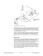
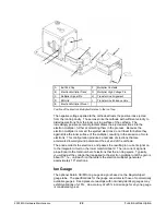
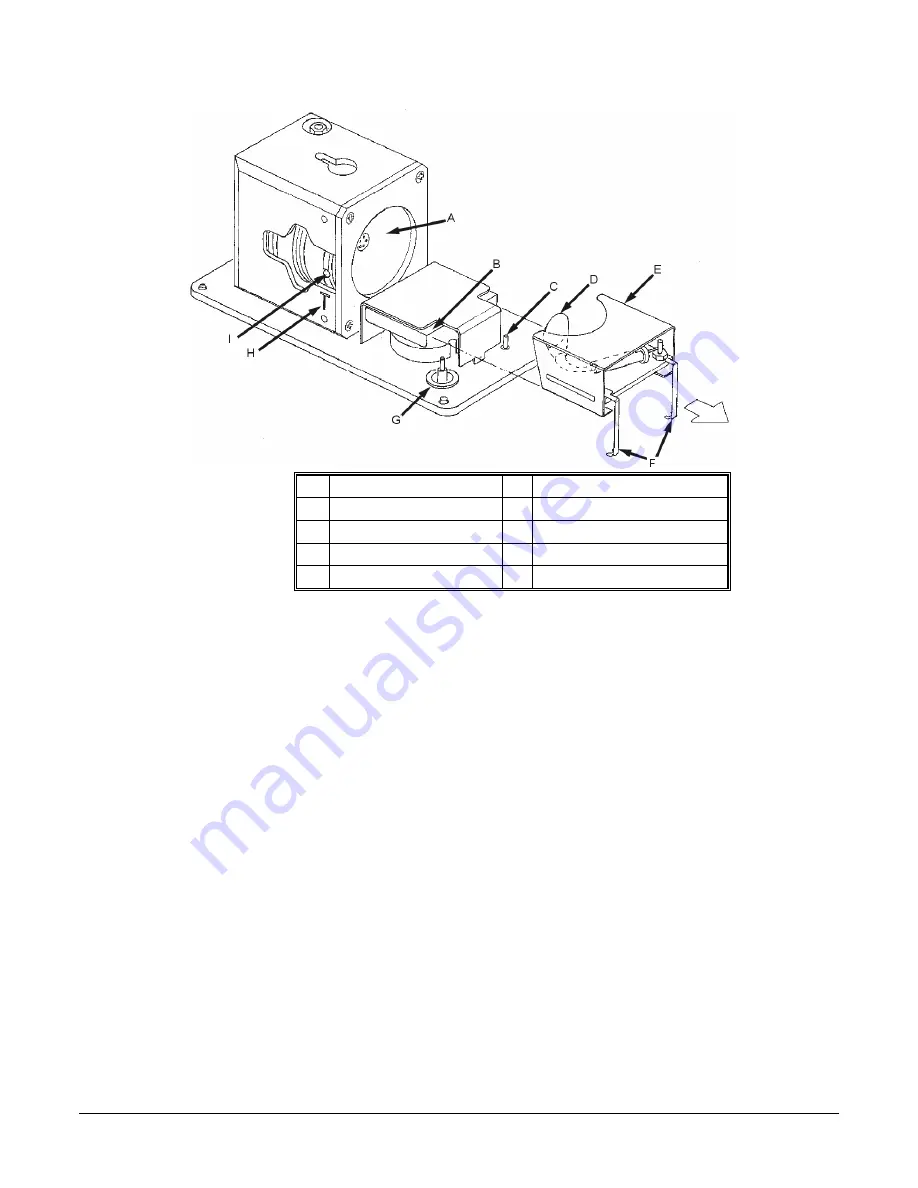
A
Exit End Cap
F
Multiplier Contacts
B
Electron Multiplier Track
G
Multiplier High Voltage Pin
C
Multiplier Signal Pin
H
Transfer Line Alignment
D
EM Grid
I
Transfer Line Entrance Hole
E
Electron Multiplier Mount
Position of the Electron Multiplier Relative to the Ion Trap
The negative voltage applied to the cathode attracts the positive ions ejected
from the ion trap cavity. These ions strike the cathode with sufficient velocity to
dislodge electrons from the inner curving surface of the cathode. The
increasingly positive potential gradient draws the ejected electrons into the
electron multiplier, further accelerating them in the process. Because the
electron multiplier is curved, the ejected electrons do not travel far before they
again strike the inner surface of the multiplier, resulting in the emission of more
electrons. This configuration produces a cascade of electrons that are
accelerated toward ground potential at the exit end of the cathode.
The anode collects the electrons, and passes the resulting ion current signal on
to the integrator circuit on the lower manifold board. The ion current signal is
proportional to the total number of electrons that the ion trap ejects. Typically,
you will adjust the voltage that is applied to the electron multiplier until the gain is
about 10
5
, i.e., until each ion that enters the electron multiplier generates
approximately 10
5
electrons.
Ion Gauge
The optional Saturn GC/MS ion gauge design is based on the Bayard-Alpert
gauge tube. The specifications for the gauge are similar to those of commercially
available gauges. Fixed pressure readings with nominally identical gauges may
exhibit variations of
±
15%. An accuracy of
±
25% in mid-range for any one gauge
is considered typical.

