Introduction to the SKF GX Series Microlog
Microlog System Connections
Microlog System Connections
WARNING! Refer to Appendix D of this manual for important restrictions when
using the CMXA 75-SL-Z2 Microlog in a Zone 2 restricted area.
Communication Set Up
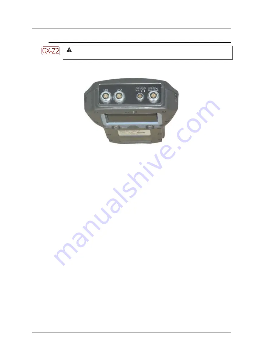
Figure 1 - 10.
Connectors on Top of the Microlog GX.
@ptitude Analyst ROUTE upload / download operations for
GX
Series Microlog utilize USB communications.
To connect your Microlog to the host computer using USB connector
:
•
Connect the supplied USB / power splitter cable between the Microlog’s
USB
Device
connector and your host computer’s USB port connector.
•
On the host computer, enable ActiveSync for USB connection. Do not set up a
partnership. When connection between the Microlog and ActiveSyn
c is established,
ActiveSync displays “Connected.”
ActiveSync communication with the GX requires specific drivers to
be installed on the host PC. Refer to the
Microsoft
ActiveSync
Communications
section, later in this chapter.
On the Microlog, the curren
t screen automatically displays a communication dialog
when the communication link is established.
•
Proceed with data transfer operations using SKF @ptitude Analyst software
Transfer
menu options.
The communication dialog remains open until the host-computer
link has been terminated
1 - 22
SKF Microlog - GX Series
User Manual


