


Conformance Check Module
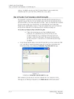
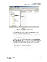
How to Set Up or Customize Conformance Test Templates
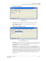
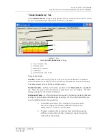
Triax Sensor
–
Check this box if a triaxial sensor is to be used. Note that checking this
box enables further parameters to be entered:
•
The direction to be associated with each channel. For the SKF 3073 M6 triaxial
accelerometer, channels X, Y and Z corresponds to direction ‘1’, ‘2’ and ‘3’
respectively.
•
Two additional
Sensitivity
entry boxes appear, totaling 3, one for each input
channel.
Also note that checking the
Triax Sensor
box, disables custom directions under the
“
Location
” sub-tab.
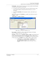
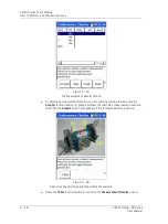
“Measurement - Locations” Sub-tab
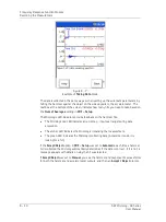
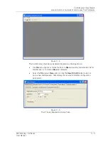
Figure 9 - 7.
Measurement – Transducer Configuration Tab.
No. Locations
– Specifies the number of measurement locations on the tested
machine. Typically, each bearing is a test location.
Directions
– Default options are
Horizontal
,
Vertical
, and
Axial
. This specifies at which
sensor orientation(s) to collect data for each measurement location. Create up to 32
custom directions by simply entering text in the
Labels
column. Use the drop-down by
clicking on an entry in the
Enabled
column to Enable, Disable or delete a direction.
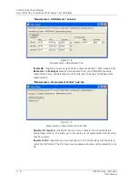
If
Triax Sensor
(on the “
Measurement -
Transducer
” tab) has
been enabled, then directions cannot be named. Instead,
Horizontal
,
Vertical
and
Axial
readings will be taken for each
location.
SKF Microlog - GX Series
9 - 7
User Manual


