


Spindle Test Module
Spindle Tests Overview
•
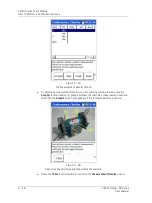
Move the sensor to the next measurement position and press Enter again. Repeat
for all the machine’s test positions.
Use up/down arrow buttons to locate a specific test position.
Press the Skip function button to skip a test location / orientation
if location is not accessible.
If desired, use left/right arrow buttons to toggle between measurement grades and
measurement values.
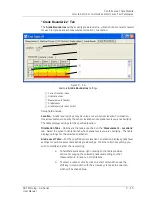
Shift < Col / Col >
Function buttons -
Our example shows three measurements (bands)
graded for each test position. The Microlog can calculate up to 64 measurements for
each position. If more than three bands are tested, hold down the Shift key (zero / up
arrow) and press the
< Col / Col >
function buttons to scroll through measurement
result columns.
Spindle Tests Overview
Real life spindle assessment requires a thorough understanding of machinery vibration,
balancing, and spindle testing techniques. This manual’s Spindle Test Module chapter
simply overviews the Microlog’s spindle assessment capabilities and introduces the
spindle assessment process.
Imbalance Test Overview
To perform an imbalance test:
•
Conn
ect the accelerometer to the Microlog input marked “CH 1.”
•
Install a balanced “master-tool” (high quality) in the spindle nose.
•
Run the spindle slowly to working temperature by step-wise increase in speed until
maximum speed is reached.
•
Power the Microlog on.
•
From the main menu, use the arrow buttons to highlight the
RUCD
icon and press
an
Enter
button. This is to determine any resonance frequencies. After
determining resonance frequency, select the Microlog’s
Spindle
module, and then
select the module’s
Resonant Frequency
test and enter the resonance frequency.
Figure 10 – 6.
Perform an Imbalance Test.
10 - 6
SKF Microlog - GX Series
User Manual


