Machinery Balancing Module
How to Set Up the Microlog for a Single
-Plane Procedure
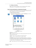
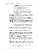
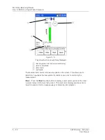
Visual
– Displays the
Set Trigger
screen that shows a graphical representation
of the tacho signal and trigger level (horizontal cursor). Use the up and down
arrow keys to move the trigger cursor to the desired trigger level (typically
between ½ and ¾ of the full trigger signal), and press
OK
. The
Set Trigger
screen closes, the
Trigger
setting changes to
Manual
and the visually specified
trigger level numerically displays in the
Trigger Level
field.
Trigger Slope
- Select
+ve
(plus) or
–ve
(minus) to determine whether the trigger
occurs on the rising or descending edge of the trigger signal.
Trigger Level –
Data entry field for manual trigger level input, or displays resulting
trigger level when the trigger level is entered visually (see above
Trigger
explanation).
Vib. Threshold
– The acceptable imbalance level you are trying to achieve. If the
vibration magnitude is greater than this threshold, the magnitude bar is colored red
when taking a reading. The bar turns green when the selected level of imbalance is
achieved.
Correction Type
– (
Polar
,
Component
, or
Fixed Weight
), Select the appropriate weight
position type.
Polar
- Specifies that weights may be placed at any placement position on the
balance plane.
Component
- (Also known as vector splitting)
(Works with
Number of
Components
field.) Specifies that weights may be placed only at designated
positions (e.g., rotors having a specific weight hole pattern, or with a specific
number of fan blades, etc.).
Fixed Weight
–
(Works with the subsequent
Fixed Weight
field.) Specifies that
you only have a specific weight value with which to work.
Num Components
– (Applies to
Correction Type / Component
weight position
measurements only.) Enter the number of weight positions, from three to
360.
The first position defaults to zero degrees, subsequent positions
are evenly spaced.
Fixed Weight
– (Applies to
Correction Type / Fixed Weight
weight position
type only.) Assumes you have only one value of weight. For example, you only
have 10 oz. weights and must use multiples of 10 oz to perform the balance.
For example, you would use one 10 oz weight for the trial run, and the
Microlog prompts you to use two 10 oz weights at one angle and one 10 oz
weight at another angle for the correction weights. Enter the weight value you
will use for the balancing process. The Microlog assumes that the
Fixed
Weight
is initially placed at 0 degrees.
The following parameters are fixed:
Weight Direction
- always Against Rotation
Posn 1 Offset
- always 0º
•
If desired, press the
Save
function button to save the balance
Setup
selections for
future use. The
Balance – Save Setup
screen displays. Refer to
Chapter 4, The
Analyzer Module
’s section on
How to Save, View, and Delete Analyzer
Measurement Results
for details on saving your measurement setups.
SKF Microlog - GX Series
5 - 7
User Manual


