Machinery Balancing Module
How to Set Up the Microlog for a Single
-Plane Procedure
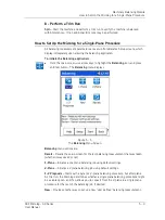
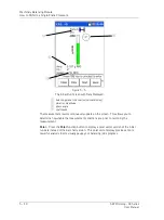
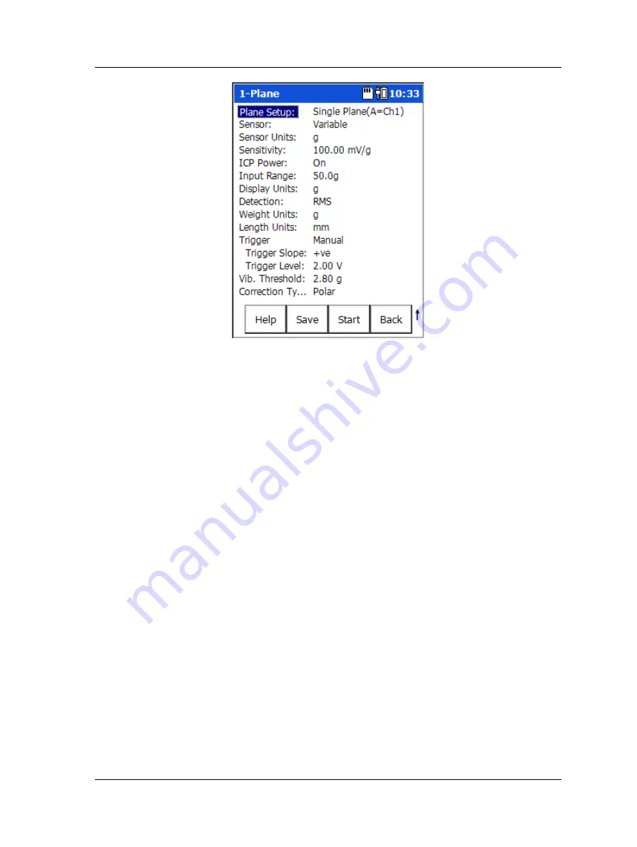
Figure 5 - 2.
A
1-Plane
Measurement Single Plane Balance Setup Screen (Expanded View).
Function Buttons
Function buttons at the bottom of the screen include:
Help
– Displays the Microlog’s context sensitive help screen.
Save
– Saves the current balancing job.
Start
– Commence the balancing run.
Back
– Return to the
Balance
menu.
Press the Shift button (0 / up arrow) to access alternate function buttons:
Expand
– Expands the measurement parameter list to display all setup parameters.
Reduce
– After expanding the measurement parameter list, press
Reduce
to reduce the
list back to only those parameters more frequently changed by analysts.
Default
– Returns parameter list settings back to their SKF factory defaults.
Balance Setup Screen Fields
•
Enter appropriate single-plane balancing setup information in the following fields:
Plane Setup
– (
Single Plane (A=CH1)
,
Two-Plane (A=CH1&B=CH2)
, or
Two-Plane
(A&B=CH1),
for single plane balancing jobs, select the
Single Plane (A=CH1)
option.
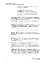
Sensor –
Select the appropriate preconfigured sensor from the setup screen’s context
sensitive sensor list. Note th
at the specified sensor type determines available options
and engineering units for subsequent setup fields. Also note that in Reduced view setup
screens, the
Sensor Units
,
Sensitivity
, and
ICP Supply
parameters only display if the
Variable
sensor is selected.
SKF Microlog - GX Series
5 - 5
User Manual


